Protecting resin-encapsulated components
a technology of resin-encapsulated components and capacitors, which is applied in the direction of fixed capacitor details, casings/cabinets/drawers, casings/cabinets/drawers, etc., can solve the problems of additional process steps and associated costs for the copper layer
- Summary
- Abstract
- Description
- Claims
- Application Information
AI Technical Summary
Benefits of technology
Problems solved by technology
Method used
Image
Examples
first embodiment
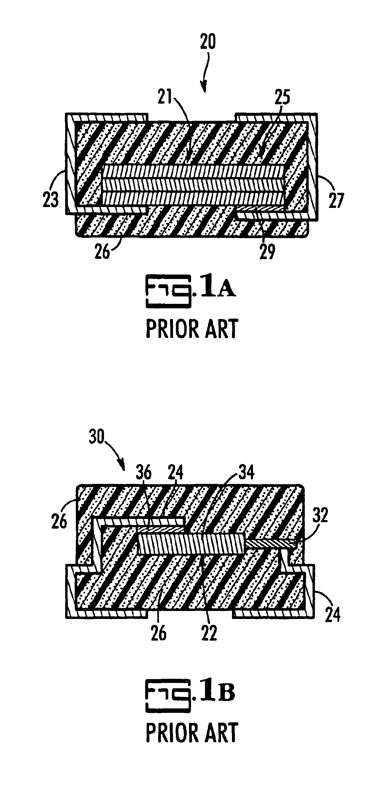
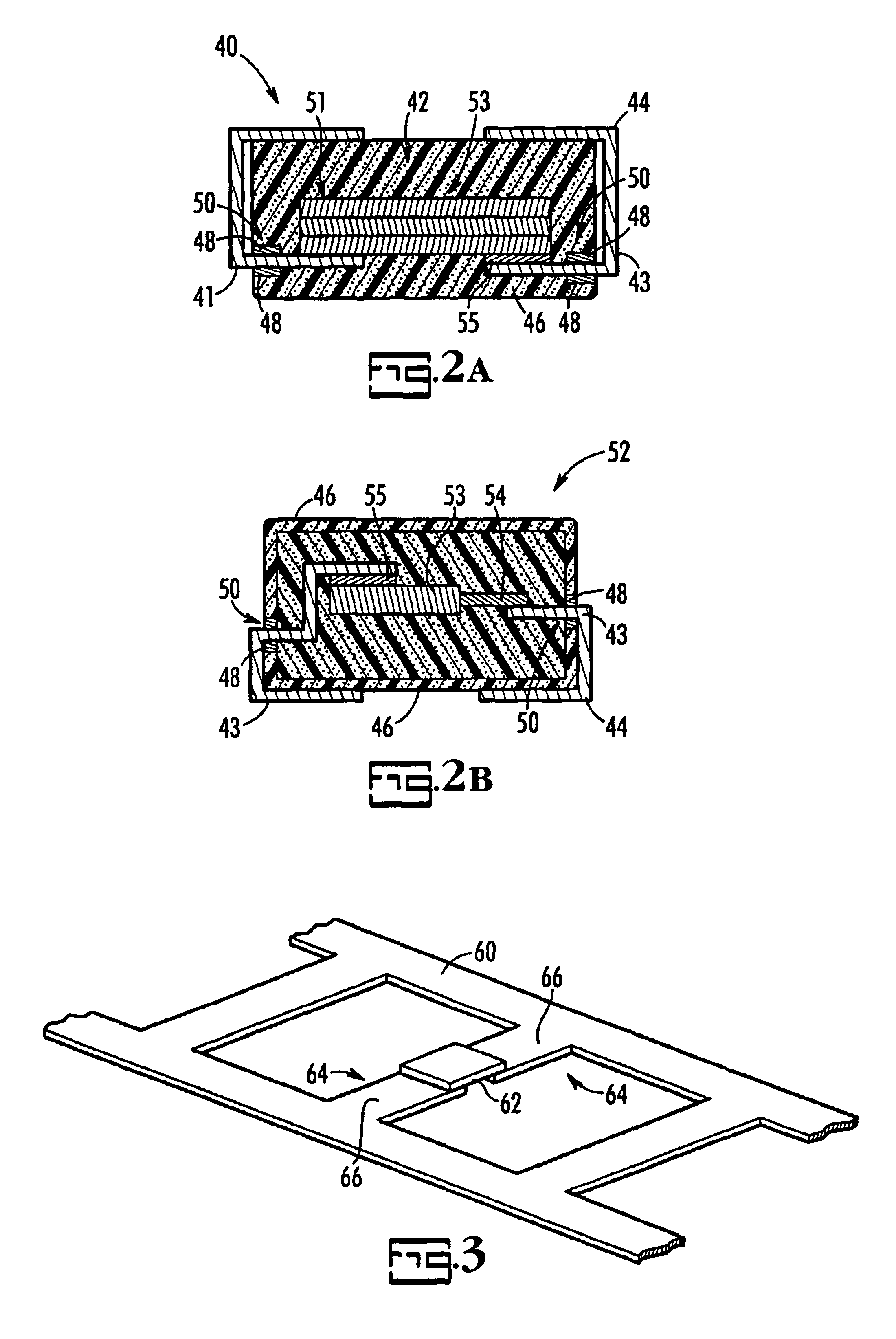
FIG. 2A is a cross-sectional view of a resin-encapsulated solid electrolytic capacitor, shown generally at 40, in accordance a first embodiment with the present invention. As previously mentioned, the capacitor element, shown generally at 42, is attached to the lead frame 44 by conventional methods, and a portion of the lead frame 44 serves as the capacitor terminals 41, 43. The capacitor 40 includes the pre-coat resin 48 that covers a solder coating-free portion, shown generally at 50, of the capacitor terminals 41, 43 and the protective resin 46 encapsulating the capacitor element 42 and the solder coating-free portion 50 of the capacitor terminals 41, 43. The protective resin 46 is molded about the capacitor element 42 and the solder coating-free portion 50 of the terminals 43.
The capacitor element 42 is connected to the lead frame 24 by welding an anode stack, shown generally at 51, to an anode terminal 41 and adhering a cathode-coated anode coupon, shown generally at 53, to a c...
second embodiment
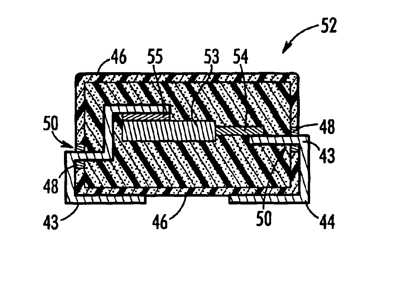
FIG. 2B is a cross-sectional view of a solid electrolytic capacitor, shown generally at 52, in accordance with the present invention. In this embodiment, the capacitor 52 includes a cathode-coated anode 53 connected to an anode riser wire 54. A portion of the lead frame 44 is connected to the anode riser wire 54 and another portion of the lead frame is connected to the cathode-coated anode body 53. The capacitor element is coated with a conductive silver paint 55. The pre-coat resin 48 covers the solder coating-free portion 50 of the capacitor terminals 43 where the protective resin 46 encapsulates the anode body 53 and the solder coating-free portion 50 of the capacitor terminals 43.
FIG. 3 is a perspective view of a lead frame 60 with a capacitor element 62 attached thereto in accordance with the present invention. As previously mentioned, the capacitor element 62 is attached to the lead frame 60 using conventional techniques. A resulting end-product capacitor has a portion 64 of t...
PUM
| Property | Measurement | Unit |
|---|---|---|
| Temperature | aaaaa | aaaaa |
| Flexibility | aaaaa | aaaaa |
Abstract
Description
Claims
Application Information
 - R&D
- Intellectual Property
- Life Sciences
- Materials
- Tech Scout
- Unparalleled Data Quality
- Higher Quality Content
- 60% Fewer Hallucinations
Browse by: Latest US Patents, China's latest patents, Technical Efficacy Thesaurus, Application Domain, Technology Topic, Popular Technical Reports.
© 2025 PatSnap. All rights reserved.Legal|Privacy policy|Modern Slavery Act Transparency Statement|Sitemap|About US| Contact US: help@patsnap.com


