Temperature controlling device for aerosol drug delivery

a temperature control device and drug technology, applied in air humidification systems, lighting and heating apparatuses, heating types, etc., can solve problems such as difficulty in making particles sufficiently small, difficulty in creating particles, and difficulty in reducing total particle size, so as to improve repeatability and efficiency of drug delivery and reduce the effect of total particle siz

Inactive Publication Date: 2005-01-18
ARADIGM
View PDF26 Cites 19 Cited by
  • Summary
  • Abstract
  • Description
  • Claims
  • Application Information

AI Technical Summary

Benefits of technology

[0023]An important advantage of the invention is that the heating device can heat a sufficient amount of air so as to evaporate a sufficient amount of carrier on aerosolized particles to make the particles consistent in size and sufficiently small as to improve the repeatability and efficiency of drug delivery.
[0024]It is an object of this invention to provide a portable air temperature controlling device able to warm the air surrounding the particles of an aerosolized drug formulation.
[0025]It is a further object of the invention to provide a drug delivery device containing such a heating element which is heated by a portable, self-contained energy source.
[0026]It is a further object of the invention to provide methods of administering aerosolized drug formulations in which the air surrounding the aerosolized formulation is warmed using a portable air temperature controlling device.
[0027]An advantage of the present invention is that it can be used for ambulatory patients.
[0028]Another object of the invention is that it makes it possible to adjust particle size by adding energy to the air surrounding the particles in an amount sufficient to evaporate carrier and reduce total particle size.

Problems solved by technology

With any of the known methods for aerosol delivery of drugs there are difficulties with respect to making the particles sufficiently small.
Along with these difficulties there are difficulties with respect to creating particles which are relatively consistent in size.
These difficulties are particularly acute when attempting to provide For systemic delivery of an aerosolized drug.
Because the stomach presents a highly acidic environment, oral preparations of peptides are unstable and readily hydrolyzed in the gastric environment.
Currently, there are no oral preparations of therapeutic peptide agents commercially available.
However, experiments by Adjei et al. have shown that the bioavailability of leuprolide when administered intranasally is relatively low.

Method used


Image

  • Temperature controlling device for aerosol drug delivery
  • Temperature controlling device for aerosol drug delivery
  • Temperature controlling device for aerosol drug delivery

Examples


example 1

[0122]A preferred embodiment of a temperature controller system 41 is shown in FIGS. 7 and 8. The system is comprised of wire 42 of total length of 130 inches. The 2.2 gram wire is split into six coils 43, 44, 45, 46, 47 and 48, each having approximately 8.4Ω resistance. Each 8.4Ω coil is then split in half forming coils 43′, 44′, 45, 46′, 47′ and 48′, making a total of 12 coils. The twelve coils are then split into two banks of six coils each that are staggered as shown in FIG. 7 which depicts their arrangement. Current flow is shown in FIG. 8 with air flow shown in FIG. 7.

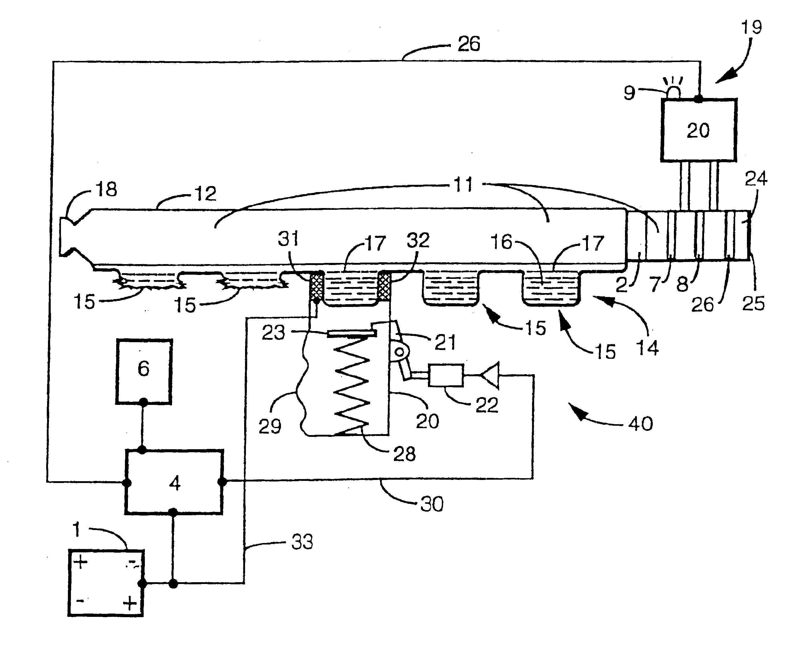
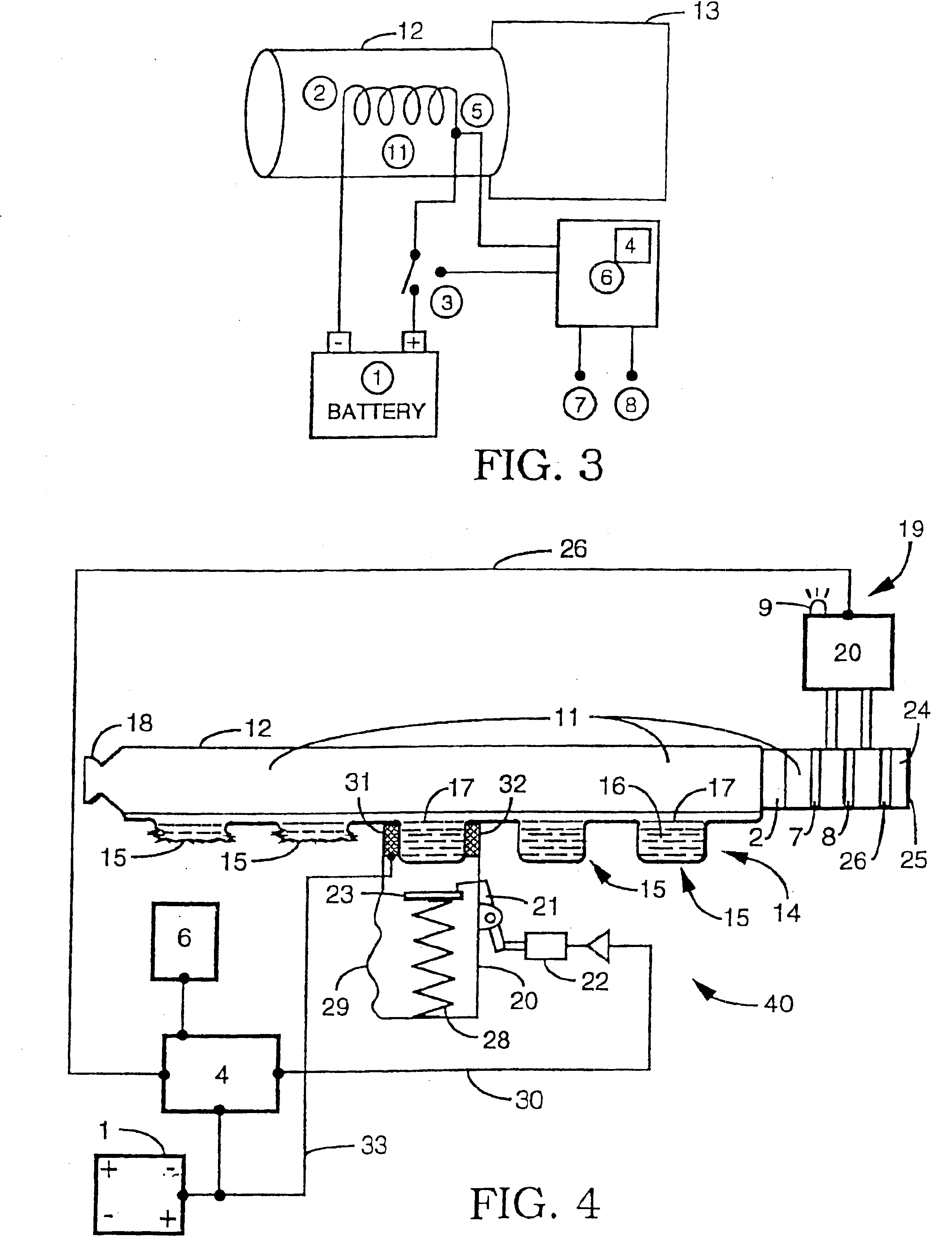
[0123]The heating element is placed inside a flow channel (11 shown in FIG. 4) (dimensions 3 cm×2 cm×1.5 cm) that is open at one end to the air, and the other end open to the aerosol generation device. The total electrical resistance of the temperature controller is ˜1.6Ω (1.4Ω for heating element coils and ˜0.2Ω for various electrical connections). A thermocouple is soldered onto one of the coils to monitor the ...

example 2

[0125]In another embodiment (not shown in the figures) the heating element is a 24 gauge wire of a nickel-copper alloy, wound in a conical coil or series of coils. The axis of the cone lies along the center of the air flow path. The temperature of the coil is monitored by a platinum RTD, which is attached to the heating element. The heating element consists of wire of total length of 80 inches. The 3.6 grams of wire is split into four conical coils, each having approximately 0.35Ω resistance. The four coils are wired in series, for a total resistance of 1.4 Ω.

[0126]The heating element is placed inside a cylindrical flow channel (dimensions 0.875″ diameter, 1.5″ long) that is open at one end to the air, and the other end open to the aerosol generation device.

[0127]To power the system, ten or less (particularly seven) AA-sized Nickel cadmium cells are connected in series to give a battery voltage of ˜8.4 V. The cells each have a capacity of 1.3 Ahr.


PUM


Abstract

A portable air temperature controlling device useful for warming air surrounding an aerosolized drug formulation is described. Warming the air of an aerosol makes it possible to reduce the size of aerosol particles produced by an aerosol generation device. Additionally, warming the air forces the size of the aerosol particles to be in the range required for systemic drug delivery independent of ambient conditions. Smaller particles can be more precisely targeted to different areas of the respiratory tract.

Description

CROSS REFERENCES[0002]This application is a continuation of U.S. application Ser. No. 09 / 839,248 filed Apr. 20, 2001 U.S. Pat. No. 6,629,526 which is a continuation of U.S. application Ser. No. 09 / 690,242 filed Oct. 16, 2000 (now U.S. Pat. No. 6.263,872, issued Jul. 24, 2001, which is a continuation of U.S. application Ser. No. 09 / 107,306 filed Jun. 30, 1998 (now U.S. Pat. No. 6,131,570, issued Oct. 17, 2000) which is a continuation-in-part of U.S. application Ser. No. 08 / 752,2946 filed Nov. 21, 1996 (now U.S. Pat. No. 5,906,202 issued May 25, 1999) which applications and patents are incorporated herein by reference and to which applications we claim priority under 35 U.S.C. §120.FIELD OF THE INVENTION[0003]This invention relates generally to portable devices and methods useful for optimizing the size distribution of a medical aerosol, and reducing the amount of variability arising from variations in ambient conditions. More specifically, this invention relates to battery powered, p...

Claims


Application Information

Patent Timeline
Patent Type & Authority Patents(United States)
IPC IPC(8): A61M15/00A61M16/00A61M16/10A61M16/16A61M11/04
CPCA61M15/00A61M15/0045A61M16/161A61M15/0051A61M16/108A61M16/1085A61M16/1095A61M16/1075A61M16/16A61M2016/0021A61M2016/0039A61M2205/3368A61M2205/52A61M2202/062A61M11/001A61M16/142
Inventor SCHUSTER, JEFFREY A.FLAIM, CHRISTOPHER J.
Owner ARADIGM
Why Eureka
Try Eureka