Apparatus for and method of producing on-demand semi-solid material for castings

Inactive Publication Date: 2005-01-25
HANJOO METAL
View PDF76 Cites 21 Cited by
  • Summary
  • Abstract
  • Description
  • Claims
  • Application Information

AI Technical Summary

Benefits of technology

One object of the present invention is to provide an improved me...

Problems solved by technology

However, the semi-solid molding (SSM) process is a capital intensive proposition tied to the use of metal purchased as pre-processed billets or slugs.
However, the viscosity of semi-solid metal is very sensitive to the slurry's temperature or the corresponding solid fraction.
The major barrier in rheocasting is the difficulty to generate sufficient slurry within preferred temperature range in a short cycle time.
Although the cost of thixocasting is higher due to the additional casting and remelting steps, the implementation of thixocasting in industrial production has far exceeded rheocasting because semi-solid feedstock can be cast in large quantities in separate operations which can be remote in time and space from the reheating and forming steps.
While the methods in (2)-(4) have been proven effective in modifying the microstructure of semi-solid alloy, they have the common limitation of not being efficient in the processing of a high volume of alloy with a short preparation time due to the following characteristics or requirements of semi-solid metals:High dampening effect in vibration.Small penetration depth for electromagnetic waves.High latent heat against rapid under-cooling.Additional cost and recycling problem to add grain refiners.Natural ripening takes a long time, precluding a short cycle time.
In fact, the greatest barrier in using methods (2)-(4), as listed above, to produce semi-solid metal is the lack of stirring.
Without stirring, it is very difficult and likely impossible to make alloy slurry with the required uniform temperature and microstructure, especially when the there is a requirement for a high volume of the alloy.
Such a process often requires that multiple billets of feedstock be processed simultaneously under a pre-programmed furnace and conveyor system, which is expensive, hard to maintain, and difficult to control.
While using high-speed mechanical stirring within an annular thin gap can generate high shear rate sufficient to break up the dendrites in a semi-solid metal mixture, the thin gap becomes a limit to the process's volumetric throughput.
The combination of high temperature, high corrosion (e.g. of molten aluminum allo...

Method used


Image

  • Apparatus for and method of producing on-demand semi-solid material for castings
  • Apparatus for and method of producing on-demand semi-solid material for castings
  • Apparatus for and method of producing on-demand semi-solid material for castings

Examples


example 1

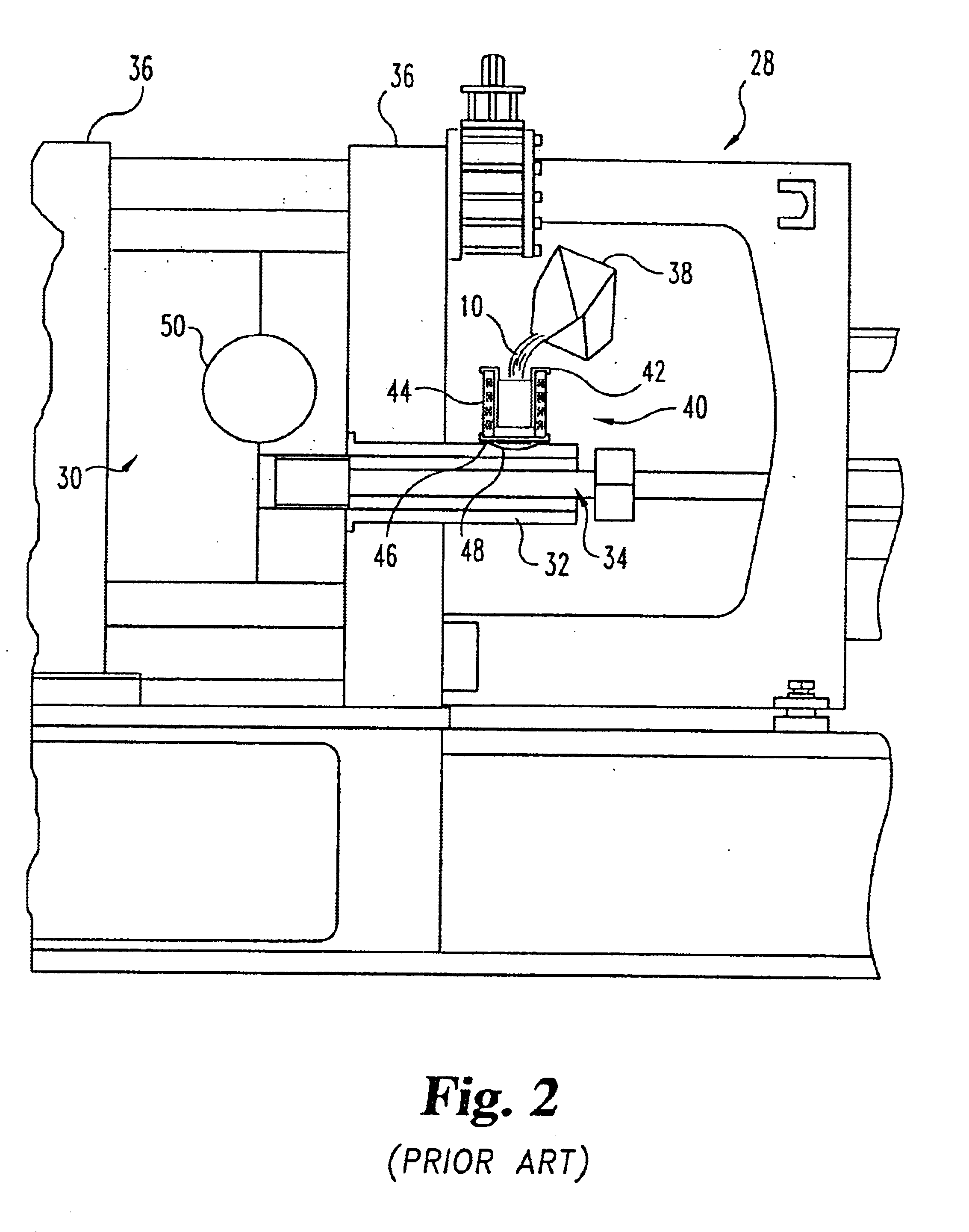
A 15 pound ingot of 356 aluminum was melted in a furnace at increasing increments of 100° F. until the alloy was in a molten state at a temperature of 1220° F. The molten alloy was then poured into a mold or transfer vessel 40 surrounded by an electrical stator (Delco 114521-3 phase) connected to a Danfuss type 3004 variable drive, which controls the voltage / frequency supplied to the stator 44. The higher the voltage / frequency, the higher the shear stress of the molten metal, which has a direct relationship to the grain size of the alpha grain structure. The available voltage was set at up to 210 volts and the actual voltage was recorded throughout the complete cycle of the process by means of a chart recorder. The temperature of the metal while being stirred in the transfer vessel was also measured and recorded with the same chart recorder as the voltage.

The molten aluminum was poured into the transfer vessel 40 and current applied to stator 44. The metal stayed in transfer vessel ...

example 2

Consistent with the teachings of the present invention and with continued to reference to the steps of the FIG. 5 flow chart, an engine-suspension bracket was fabricated. The original design of this bracket used cast iron and there was an interest in reducing its weight for improved fuel efficiency for the vehicle. A decision was made by the auto maker to use an aluminum alloy for the bracket. However, the aluminum bracket made with conventional high-pressure die casting failed to pass the evaluation because of its low elongation, which could lead to a catastrophic failure in a collision. When the apparatus and process steps of the present invention were used for the fabrication of this bracket, it was determined that all of the desired material properties for the bracket could be achieved. The specifics of the actual process used for the fabrication of this engine-suspension bracket, according to the present invention, are outlined below.

Al 357 is melted into a molten state in a fu...


PUM

PropertyMeasurementUnit
Timeaaaaaaaaaa
Timeaaaaaaaaaa
Timeaaaaaaaaaa

Abstract

A method of producing on-demand, semi-solid material for a casting process includes the steps of first heating a metal alloy until it reaches a molten state and maintaining that molten state within a desired temperature range. The next step is to ladle out a portion of the molten alloy and transfer it into a processing vessel. In one arrangement the vessel is configured with its own cooling arrangement so as to begin the solidification process for the molten alloy. In another embodiment, a thermal jacket is used to facilitate the cooling of the vessel and accordingly the cooling of the molten alloy. The next step is to apply an electromagnetic field to the molten alloy in order to create a stirring action which results in a desired flow pattern of the molten alloy within the vessel. The electromagnetic stirring begins as soon as the molten alloy is placed in the vessel and continues while the cooling continues in order to create a slurry billet of the desired metallurgical composition. The final step is to discharge the slurry billet from the vessel directly into a shot sleeve of a casting machine. The apparatus related to the described method includes a vessel which is constructed and arranged for receipt of the molten alloy. A robotic arm is provided in one embodiment for moving the vessel into a stator and then from the stator to the discharge location. In another embodiment, pneumatic cylinders are used in cooperation with structural linkages to effect movement of the vessel first into the stator and then from the stator to the discharge location. Suitable cooling arrangements for the vessel include cooling lines within the vessel, the passage of cooling air between the stator and the vessel, and the use of a thermal jacket.

Description

BACKGROUND OF THE INVENTIONThe present invention relates in general to an apparatus which is constructed and arranged for producing an “on-demand” semi-solid material for use in a casting process. Included as part of the overall apparatus are various stations which have the requisite components and structural arrangements which are to be used as part of the process. The method of producing the on-demand semi-solid material, using the disclosed apparatus, is included as part of the present invention.More specifically, the present invention incorporates electromagnetic stirring and various temperature control and cooling control techniques and apparata to facilitate the production of the semi-solid material within a comparatively short cycle time. Also included are structural arrangements and techniques to discharge the semi-solid material directly into a casting machine shot sleeve. As used herein, the concept of “on-demand” means that the semi-solid material goes directly to the cas...

Claims


Application Information

Patent Timeline
IPC IPC(8): B22D27/02B22D1/00B22D17/00B22D17/10B22D17/28B22D17/30
CPCB22D17/007B22D17/10C22C1/005B22D17/30Y10S164/90C22C1/12
Inventor NORVILLE, SAMUEL M. D.LOMBARD, PATRICK J.LU, JIANWANG, SHAUPOH
Owner HANJOO METAL
Why Eureka
Try Eureka