System and method for harvesting electric power from a rotating tire's static electricity

a technology of electric power and static electricity, which is applied in the field of system and method for harvesting electric power from rotating tires static electricity, can solve the problems of obviating many complications of tire electronics solely powered by batteries, and achieve the effect of facilitating greater functionality of tire electronics and reducing the amount of required signal hardwar

Active Publication Date: 2005-01-25
MICHELIN RECH & TECH SA
View PDF40 Cites 34 Cited by
  • Summary
  • Abstract
  • Description
  • Claims
  • Application Information

AI Technical Summary

Benefits of technology

Another advantage of the present subject matter is that a tire monitoring system is provided that reduces the amount of required signal hardware relative to conventional tire monitoring systems. By providing a tire monitoring system that is self-powered, no scavenger antennas or multiple receiver locations with additional hardwire connections are required. Components of such a tire monitoring system can be integrated within each individual tire structure on a given vehicle such that a single receiver (typically located in a vehicle cabin) is capable of acquiring information transmitted by each tire's integrated electronics.
Yet another advantage of the present subject matter is that there are fewer limitations regarding the type and amount of electronic equipment capable of utilization within tire and wheel as

Problems solved by technology

Although batteries and battery-operated devices may still be incorporated with aspects of the present subject matter, many compli

Method used


Image

  • System and method for harvesting electric power from a rotating tire's static electricity
  • System and method for harvesting electric power from a rotating tire's static electricity
  • System and method for harvesting electric power from a rotating tire's static electricity

Examples


Embodiment Construction

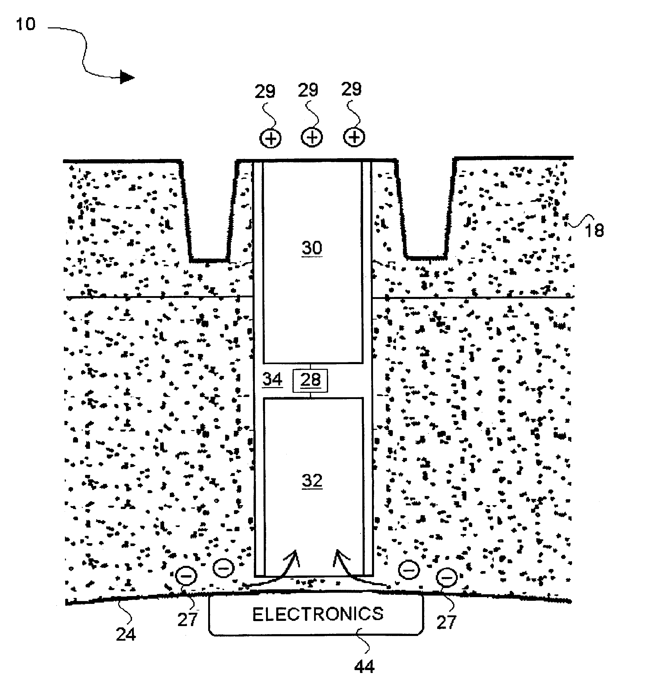
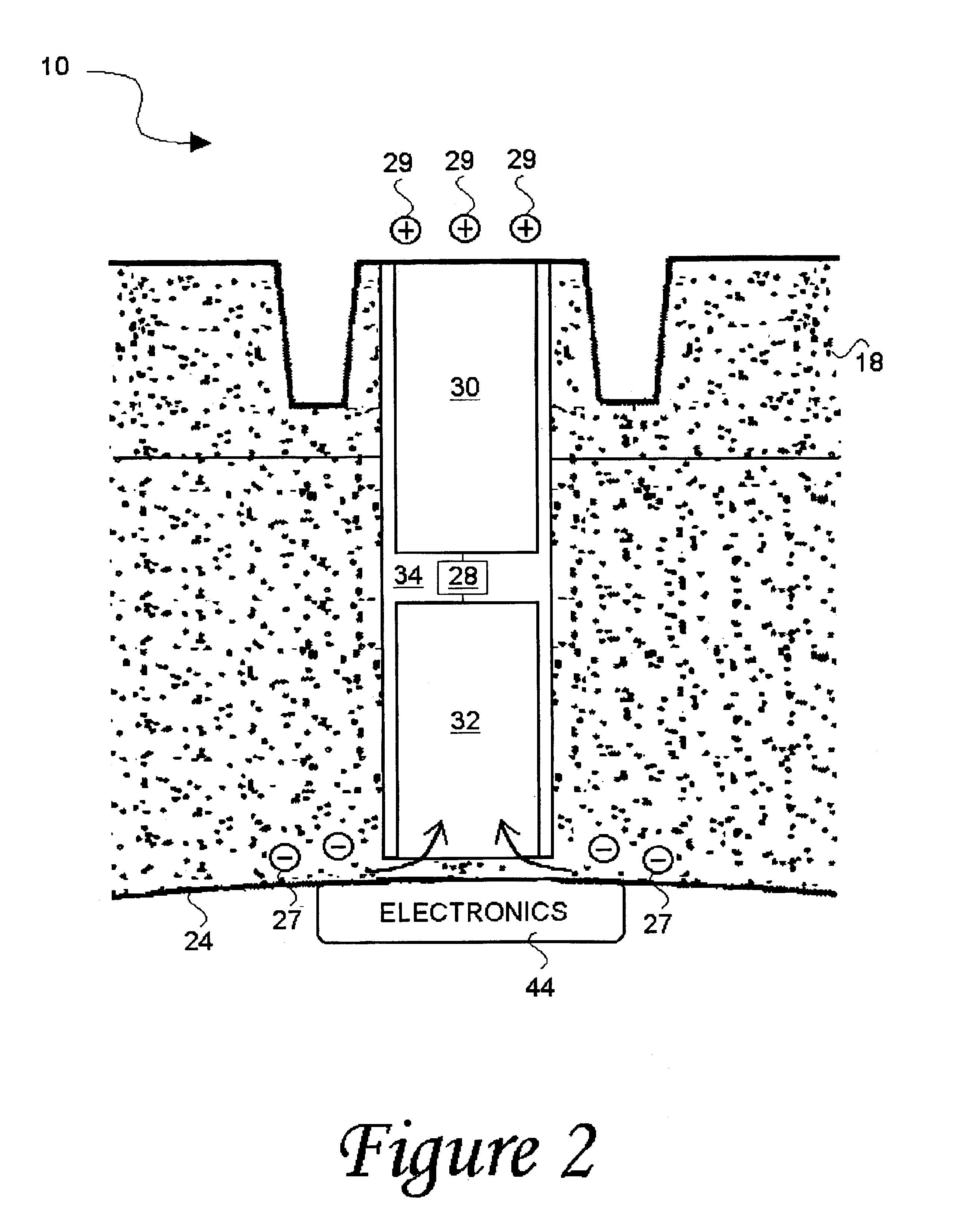
As discussed in the Brief Summary of the Invention section, the present subject matter is particularly concerned with a system and method for harvesting power within a tire structure while simultaneously providing features to dissipate the buildup of electric charge from a tire structure. Sufficient accumulations of the harvested electric charge can then be used to power electronic systems, examples of which include components for identifying various physical tire parameters as well as radio frequency (RF) transmission devices and others.

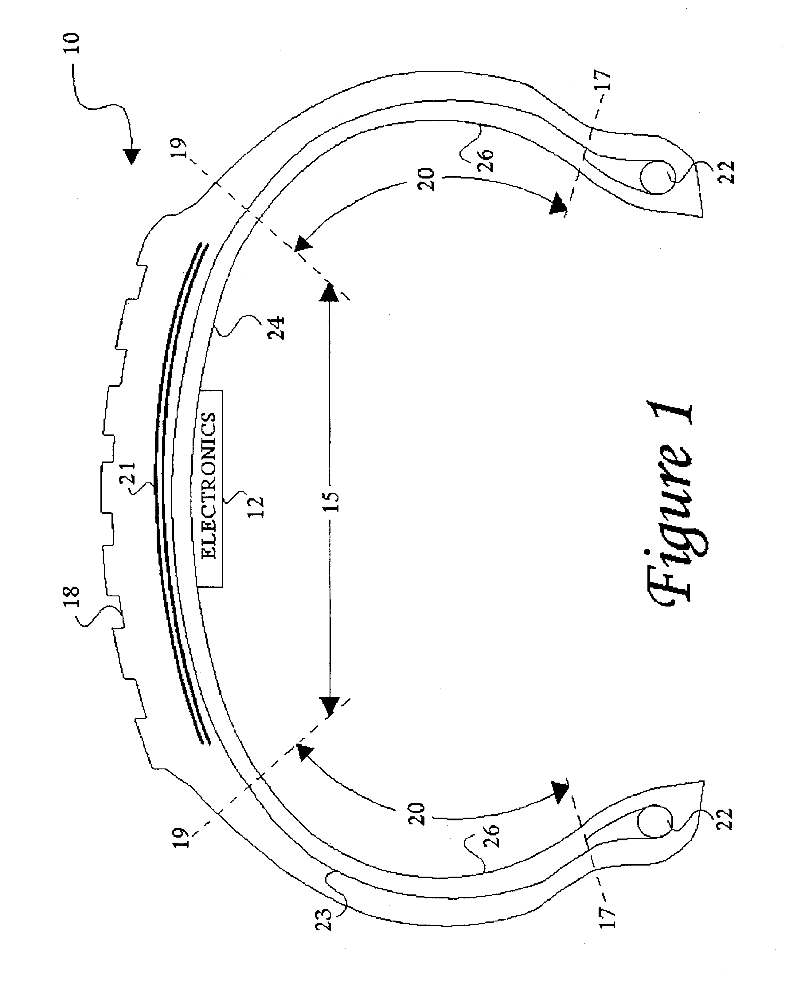
Features for dissipating the buildup of static electricity from within a tire structure include portions of conductive material interposed between the inner and outer surfaces of a tire structure. Exemplary aspects of such portions of conductive material and their association with a tire structure are illustrated with respect to FIGS. 1-3. An energy storage device and other power harvesting circuitry for use with a conductivity path as defined by po...


PUM


Abstract

A power harvesting solution concerns a generally non-conductive tire structure that is formed with at least one defined conductivity path through which static electricity accumulated in the tire structure during tire rotation can dissipate to ground. Such conductivity path is formed from a portion of conductive material that may be partially surrounded by additional insulative material to restrict the flow of electric charge to ground. An energy storage device, such as a capacitor or rechargeable battery, is coupled with the conductivity path and configured to store selected amounts of the electric charge dissipating through the conductivity path. Various diode elements may be provided in combination with the energy storage device to prevent reverse discharging of and to provide voltage protection for the energy storage device. Sufficient accumulations of such harvested energy can then power tire electronic systems, including various condition-responsive devices (i.e., sensors, etc.) a revolution counter, a radio frequency (RF) device, a rechargeable battery or a lighting device.

Description

FIELD OF THE INVENTIONThe present invention generally concerns tire electronics assemblies that are self-powered via charges that accumulate during conventional tire rotation. More particularly, a pneumatic tire structure with generally non-conductive portions may be constructed with at least one electrically conductive segment formed through the tire structure and tread portion to provide a channel through which built-up static electricity can dissipate to ground while some of the channeled static electricity is simultaneously captured in an energy storage device. Sufficient accumulations of such harvested energy can then power tire electronic systems, including various condition-responsive devices (i.e., sensors, etc.), radio frequency (RF) transmitters, and other components.BACKGROUND OF THE INVENTIONThe incorporation of electronic devices with pneumatic tire structures yields many practical advantages. Tire electronics may include sensors and other components for relaying tire i...

Claims


Application Information

Patent Timeline
IPC IPC(8): B60C19/00B60C19/08B60C13/00B60C11/00B60C23/04B60C23/02
CPCB60C11/00B60C13/00B60C23/0493B60C19/08B60C23/041B60C19/00B29D2030/0094
Inventor ADAMSON, JOHN DAVIDO'BRIEN, GEORGE PHILLIPS
Owner MICHELIN RECH & TECH SA
Why Eureka
Try Eureka