Image display apparatus

a technology of display apparatus and display screen, which is applied in the direction of instruments, computing, electric digital data processing, etc., can solve the problems of reducing display quality, unable to obtain sufficient image contrast, and accumulating charge in non-activated leds connected to unselected common source lines, so as to prevent any display time lag, reduce wiring area, and increase wiring layout options

Inactive Publication Date: 2005-01-25
NICHIA CORP
View PDF40 Cites 13 Cited by
  • Summary
  • Abstract
  • Description
  • Claims
  • Application Information

AI Technical Summary

Benefits of technology

The image data correction section of the image display apparatus of the present invention is provided with buffer memory to store at least one line of correction data. The image data correction section can read out the next line of correction data from the correction data memory section while it outputs one line of corrected image data to the horizontal driver section. This prevents any display time lag between lines due to image data correction.
In the image display apparatus of the present invention, shift registers can be provided as buffer memory, and correction data can be read via the shift registers by direct sequential shifting one bit at a time. This eliminates the need for data bus line branching to transfer correction data to buffer memory in the correction data memory section, and it also eliminates the need for an address bus to select buffer memory. Therefore, wiring area can be reduced and wiring layout options can be increased.
Still further, in the image display apparatus of the present invention, two stages of interconnected registers can be provided as buffer memory. When the first register outputs one line of correction data, the next line of correction data is read into the second register. Each time output and input of one line of correction data is completed, correction data from the second register can be transferred to the first register. With this system, image data can be corrected with a simple circuit structure.
In the image display apparatus described above, the second register can be a shift register, and correction data can be read by direct sequential shifting one bit at a time. This eliminates the need for data bus line branching to transfer correction data, and it also eliminates the need for an address bus to select buffer memory.
The image display apparatus of the present invention can use LEDs as the light emitting devices. In this image display apparatus, LED display peripheral circuit structure can be simplified and the display apparatus can made compact.
Finally, the image display apparatus of the present invention can display images by dividing the entire image into parts. Since the image display apparatus of the present invention can simplify peripheral circuit structure, it is suitable for use in image data units which display part of an entire image, for example, it is suitable for LED units used in large-scale LED displays.

Problems solved by technology

However, when LEDs connected to a selected common source line were activated in related art apparatus, charge accumulated in non-activated LEDs connected to unselected common source lines.
As a result of this problem, LEDs controlled to be off emitted low levels of light and sufficient image contrast could not be obtained.
These types of effects caused display quality degradation.
However, since correction data were stored in ROM in related art apparatus, correction data could not be re-written.
Consequently, related art apparatus had problem in that it was necessary to provide a re-writable memory device separate from the ROM when different correction data were required.
In addition to these problems, both the address bus 111 and the data bus 112 must branch to, and connect with, each of then driver IC's 104(1 to n), thereby making wiring complex and peripheral circuitry large in area.

Method used


Image

  • Image display apparatus
  • Image display apparatus
  • Image display apparatus

Examples


Embodiment Construction

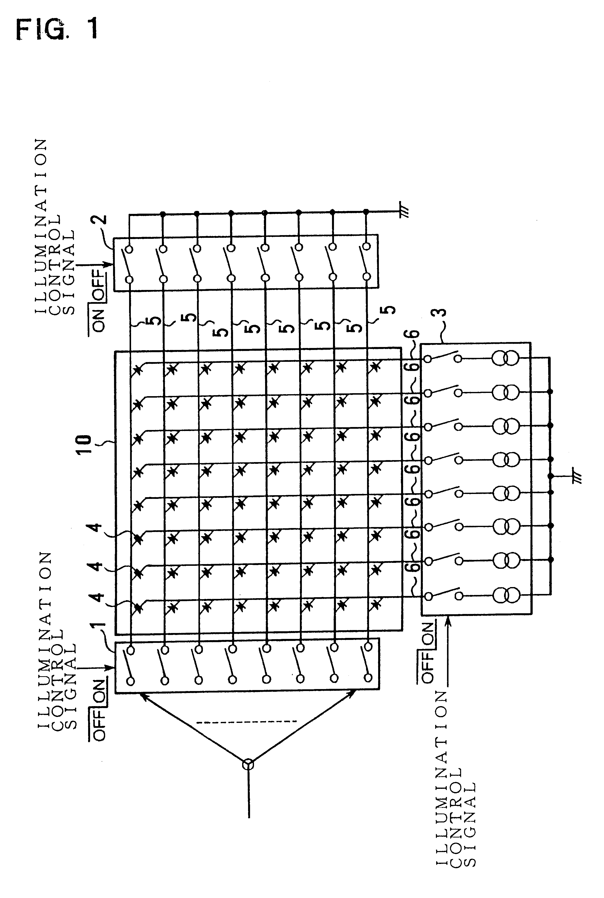
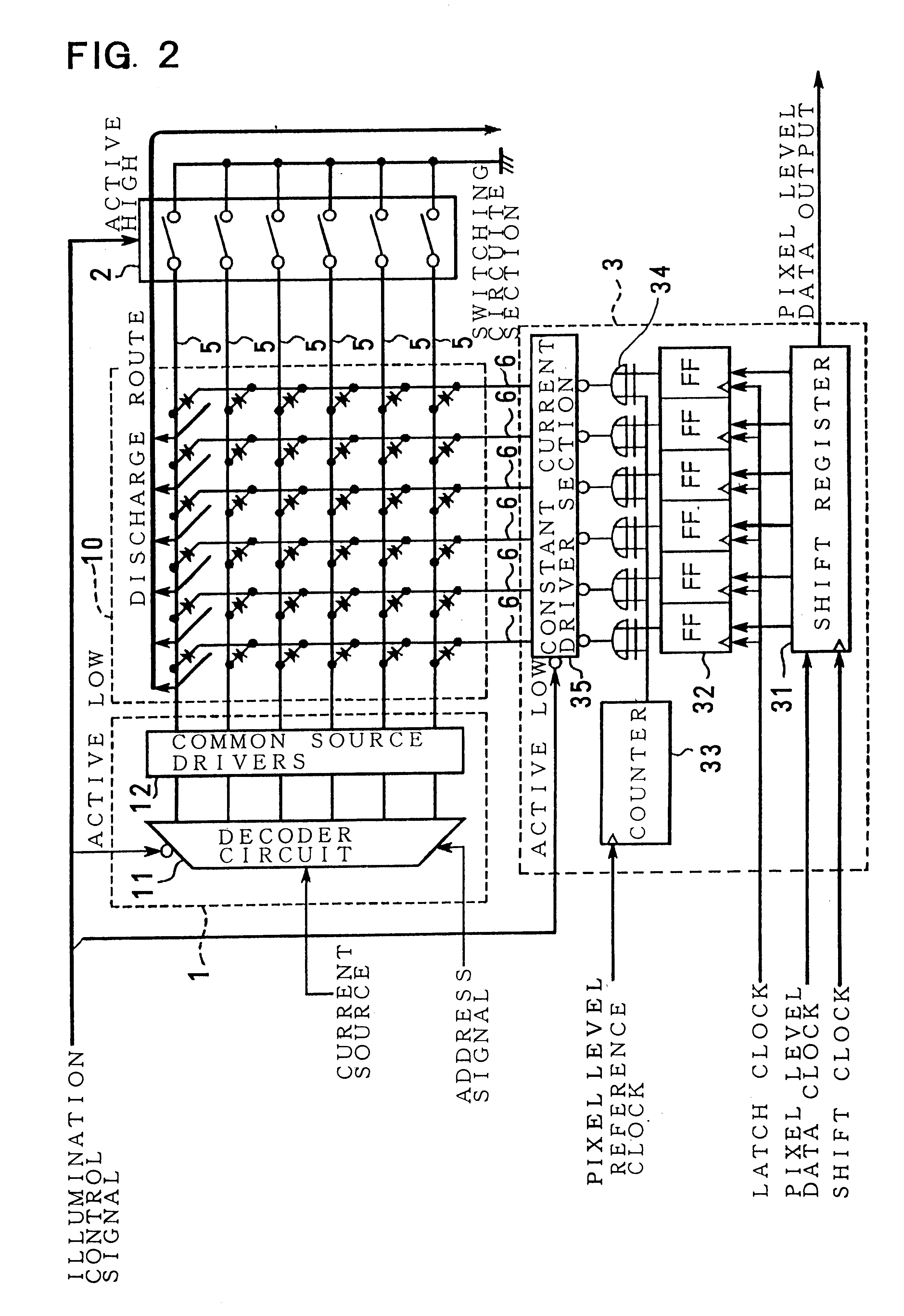
FIG. 1 is a conceptual drawing illustrating an image display apparatus provided with a switching circuit section to discharge accumulated charge in the dot matrix. The display apparatus of FIG. 1 is provided with an LED dot matrix 10, a current source switching circuit 1, a constant current control circuit section 3, and a switching circuit section 2. The display apparatus of FIG. 1 uses LEDs as light emitting devices, but devices other than LEDs may also be used as the light emitting devices.(1) The LED dot matrix 10 is a plurality of LEDs 4 arranged in a m-line, n-column matrix. The cathode of each LED 4 in each column is connected to a current line 6. The anode of each LED 4 in each line is connected to a common source line 5.(2) The current source switching circuit 1 is provided with in-switching circuits which correspond to, and are connected to, each respective common source line 5. The current source switching circuit 1 connects a current source to the common source line 5 se...


PUM


Abstract

The image display apparatus is provided with a dot matrix of light emitting devices, driver circuitry, and switching circuitry. The dot matrix is a plurality of light emitting devices arranged in an in-line by n-column matrix, and one terminal of each light emitting device in each line is connected to a common source line. Driver circuitry controls light emitting devices active or inactive depending on an input illumination signal. In the active state, switching circuitry floats common source lines, and in the inactive state, discharges all common source lines to ground.

Description

This application is based on applications No. 11-194551 filed in Japan on Jul. 8, 1999, No. 11-302493 filed in Japan on Oct. 25, 1999, and No. 11-303134 in Japan on Oct. 25, 1999, the contents of which incorporated hereinto by references.BACKGROUND OF THE INVENTIONThe present invention relates to a display apparatus provided with a plurality of light emitting devices such as light emitting diodes arrayed in a matrix display panel, and to its method of operation.Currently, bright red, green, and blue (RGB) light emitting diodes (LEDs) of 1000 mcd or more have been developed, and fabrication of large-scale LED displays has become possible. These LED displays have features such as low power consumption, lightness in weight, and the possibility for thin panel display. Further the demand for large-scale displays, which can be used outdoors, has increased dramatically.Practical large-scale LED displays are configured to fit the installation space by assembling a plurality of LED units. An...

Claims


Application Information

Patent Timeline
Patent Type & Authority Patents(United States)
IPC IPC(8): G09G3/32G09G3/20
CPCG09G3/32G09G3/3216G09G3/3275G09G3/3283G09G2300/06G09G2370/04G09G2310/027G09G2310/061G09G2320/0285G09G2320/043G09G2310/0251G09G3/20
Inventor TSUJI, RYUHEI
Owner NICHIA CORP
Why Eureka
Try Eureka