Method, optical device, and system for optical fiber transmission

a technology of optical fiber and optical fiber, applied in the field of optical device, optical device, and optical fiber transmission system, can solve the problems of waveform distortion, frequency chirping, and limited transmission capacity of optical fiber, and achieve the effect of increasing the input power of optical signals

Inactive Publication Date: 2005-01-25
FUJITSU LTD
View PDF11 Cites 96 Cited by
  • Summary
  • Abstract
  • Description
  • Claims
  • Application Information

AI Technical Summary

Benefits of technology

In accordance with a third aspect of the present invention, there is provided an optical device to which an optical signal compressed on the time axis as propagating in an optical fiber is supplied. This optical device comprises a distributed feedback (DFB) laser and a circuit for supplying a current to the DFB laser so that the DFB laser oscillates at a first wavelength. The optical signal has a second wavelength different from the first wavelength. As a result, the DFB laser can apply a gain saturated in concert with an increase in input power to the optical signal.

Problems solved by technology

However, a transmission capacity by the optical fiber is actually limited by a system design.
The most important limitation is due to waveform distortion by chromatic dispersion occurring in the optical fiber.
A change in the refractive index modulates the phase of an optical signal propagating in an optical fiber, resulting in the occurrence of frequency chirping which changes a signal spectrum.
Spectral broadening due to SPM occurs to cause further enlargement of the waveform distortion due to chromatic dispersion.
Thus, in optical fiber communication, the waveform degradation due to the dispersion of an optical fiber or the nonlinear optical effects in an optical fiber becomes a large factor of transmission limit.
Accordingly, a transmission distance in transmission of a high-speed signal is remarkably limited.
In the conventional dispersion compensating methods or the prechirping method, the transmission distance cannot be sufficiently increased.

Method used


Image

  • Method, optical device, and system for optical fiber transmission
  • Method, optical device, and system for optical fiber transmission
  • Method, optical device, and system for optical fiber transmission

Examples


Embodiment Construction

Some preferred embodiments of the present invention will now be described in detail with reference to the attached drawings. The same reference numerals in similar drawings denote like or similar parts.

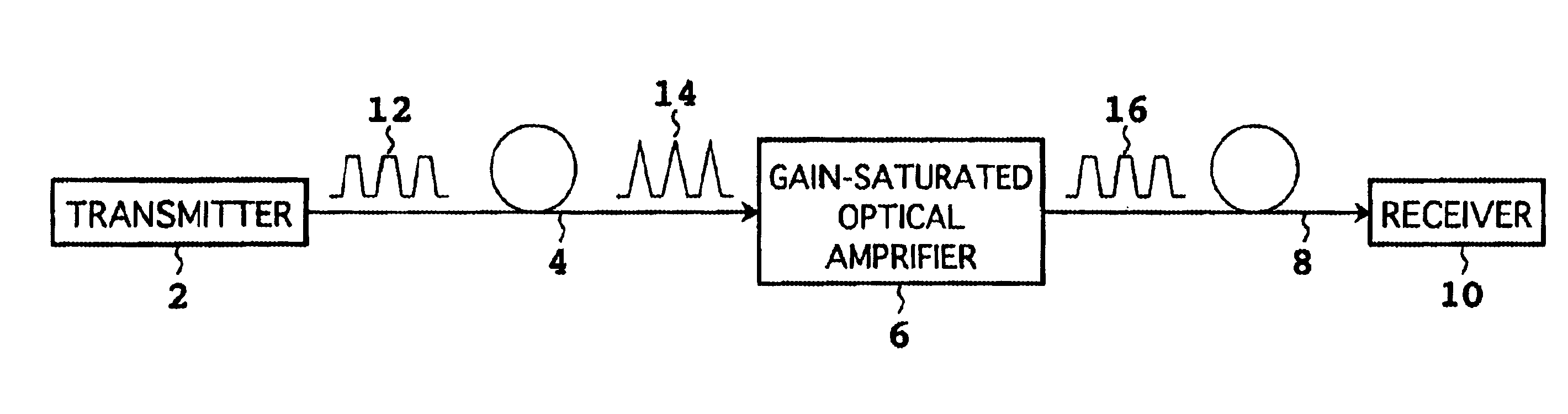
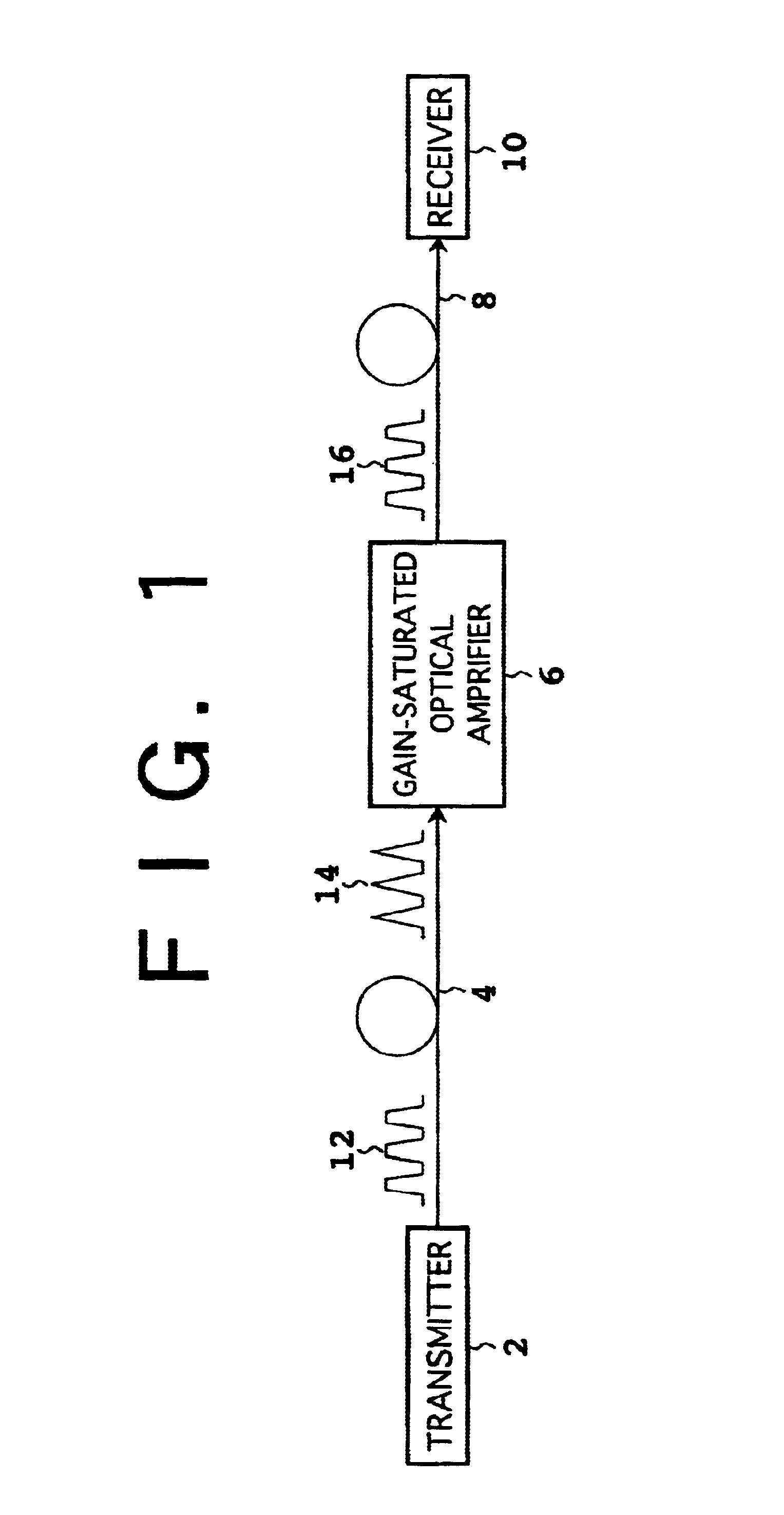
FIG. 1 is a block diagram showing a first preferred embodiment of the system according to the present invention. This system includes a transmitter 2, a gain-saturated optical amplifier 6 connected to the transmitter 2 by a first optical fiber 4, and a receiver 10 connected to the optical amplifier 6 by a second optical fiber 8. The transmitter 2 outputs a pulsed optical signal to the first optical fiber 4 as shown by reference numeral 12. The first optical fiber 4 is provided so that the optical signal output from the transmitter 2 is compressed on the time axis as shown by reference numeral 14 as propagating in the first optical fiber 4. A compressed optical signal output from the first optical fiber 4 is supplied to the optical amplifier6. The optical amplifier 6 has a saturated ga...


PUM


Abstract

The present invention relates to a method for optical fiber transmission which can increase a transmission distance. A first optical fiber having dispersion is first provided. An optical signal is next supplied to the first optical fiber so that the optical signal is compressed on the time axis as propagating in the first optical fiber. In the case that the dispersion is normal dispersion, for example, prechirping is performed so that the optical signal has down-chirp. A compressed optical signal output from the first optical fiber is supplied to an optical device having a saturated gain. According to this method, the transmission distance can be increased by the effective combination of compression of the optical signal and waveform shaping by the optical device.

Description

BACKGROUND OF THE INVENTION1. Field of the InventionThe present invention relates to a method, optical device, and system for optical fiber transmission.2. Description of the Related ArtOwing to recent developments of low-loss silica optical fibers, various optical fiber communication systems each using such an optical fiber as a transmission line have been put to practical use. The optical fiber itself has a very wide band. However, a transmission capacity by the optical fiber is actually limited by a system design. The most important limitation is due to waveform distortion by chromatic dispersion occurring in the optical fiber. Further, the optical fiber attenuates an optical signal at a rate of about 0.2 dB / km, for example. Loss of the optical signal due to this attenuation has been compensated for by adopting an optical amplifier such as an erbium doped fiber amplifier (EDFA) that is a typical example.The chromatic dispersion that is often referred to simply as dispersion is a ...

Claims


Application Information

Patent Timeline
Patent Type & Authority Patents(United States)
IPC IPC(8): H04B10/18H04B10/07H04B10/2507H04B10/2525H04B10/2531H04B10/2543H04B10/299
CPCH04B10/2531H04B10/25133
Inventor WATANABE, SHIGEKI
Owner FUJITSU LTD
Why Eureka
Try Eureka