Eureka AIR delivers breakthrough ideas for toughest innovation challenges, trusted by R&D personnel around the world.

Interior mirror assembly for a vehicle incorporating a solid-state light source

a technology of interior mirror and solid-state light source, which is applied in the direction of fixed installation, lighting and heating equipment, lighting support devices, etc., can solve the problems of unsafe driving conditions for the vehicle driver, driver or passenger groping clumsily, and failure to provide the illumination of many other controls needed to fully operate the vehicl

Inactive Publication Date: 2005-02-01
BOS BRENT J +2
View PDF160 Cites 176 Cited by
  • Summary
  • Abstract
  • Description
  • Claims
  • Application Information

AI Technical Summary

Benefits of technology

The low level light emitting source avoids causing glare visible by the vehicle driver, and preferably provides illumination of less than about 60 lux, preferably less than about 25 lux, and most preferably less than about 10 lux at the locations desired to be illuminated. Preferably, the light emitting source is a solid state source such as a light emitting diode although vacuum fluorescent sources, electroluminescent sources (including both organic electroluminescent sources and inorganic electroluminescent sources), and semiconductor laser sources may also be used. The preferred light emitting diode is preferably mounted in a hollow mounting adaptor telescopingly receiving the diode in one end and optionally being closed by a lens at the other end. The adaptor is preferably mounted in the bottom wall of the mirror case to the rear of the reflective rear element or in a wall of an interior vehicle lamp assembly in a manner that avoids creation of unwanted glare. If desired, two or more of such low level light emitting sources may be incorporated in the mirror assembly at spaced locations for directing light at a desired or different portions of the vehicle interior, or may be grouped to provide more intense and / or broader area local illumination.
In the most preferred form, the light emitting diode low level light emitting source provides a maximum illumination of about 0.2 to 4.0 lux at about 22 to 26 inches at about 20 mA to about 50 mA current, or less, and about 2.0 volts to about 5.0 volts, or less. The diode is typically connected in series with a suitable electrical resistor (typically less than about 1500 ohms and greater than about 100 ohms in electrical resistance; more preferably, less than about 1000 ohms and greater than about 200 ohms in resistance) to reduce the current to the diode and, preferably, to enable connection to an ignition voltage of the vehicle (typically 9 to 16 volts with about 12 volts nominal) and may be controlled by the ignition switch of the vehicle power system and / or by a rheostat / dimmer switch located, for example, at the headlight control switch for the vehicle.
The interior rearview mirror assembly or interior vehicle lamp assembly incorporating the low level light emitting source of the present invention provides numerous advantages over prior known vehicle instrumentation or control illumination sources. The present light emitting source may be directed to specific areas of instrumentation or control switches and provides illumination of controls previously unlit such as shift levers, parking brake levers, ashtrays, cupholders, HVAC controls, radio knobs and the like. The light emitting source is small and compact in size and highly durable having a life span typically longer than the operational lifetime of the vehicle itself, and may be mounted in confined locations without concern for access for repair or replacement. The light emitting source preferably provides a defined pattern of light such as a cone of light which may be directed as desired without any separate reflector, separate lens, separate collimator, etc.; has low power consumption requirements and thus, desirably and optionally, may be illuminated whenever the ignition switch of the vehicle is at the accessory on position or at the ignition on position, day and night; creates virtually no heat within the vehicle; and is amenable to mounting in many areas for illumination of desired controls. Moreover, the light emitting source avoids the creation of unwanted, unsafe glare which could otherwise distract or temporarily disable a vehicle driver. The light emitting source may also be used separately or together with other low level light emitting sources, can be used with virtually any mirror assembly or interior lamp assembly and can be adjusted if mounted on or within the mirror case, or fixed in position on or within the mirror support such as on or within the mirror mounting arm or the coupling channel member, a separate instrument pod, or an interior lamp assembly. The light emitting source can also provide a variety of pleasing illumination colors without the need for separate coloring filters.

Problems solved by technology

However, these conventional lighting sources fail to provide illumination of many other controls needed to fully operate the vehicle, leaving the driver or passenger to grope clumsily at night or in low light conditions to find items such as an ashtray, door handle, seat or window switch, heater control, cup holder, or the like.
Alternately, the person may switch on a general overhead light to find a particular control or handle but creating high levels of unwanted glare causing unsafe driving conditions for the vehicle driver.
Use of such a conventional overhead or other general illumination light emitting source has typically included an incandescent bulb requiring high power levels and creating additional heat within the vehicle.
Such incandescent light bulbs are also subject to short life spans and frequent failure.
Moreover, use of such conventional lighting cannot be continuous during night vehicle use because of the high glare levels produced, thereby leaving many controls within the vehicle unidentified for most night driving or other low level light conditions.

Method used


Image

  • Interior mirror assembly for a vehicle incorporating a solid-state light source
  • Interior mirror assembly for a vehicle incorporating a solid-state light source
  • Interior mirror assembly for a vehicle incorporating a solid-state light source

Examples


Embodiment Construction

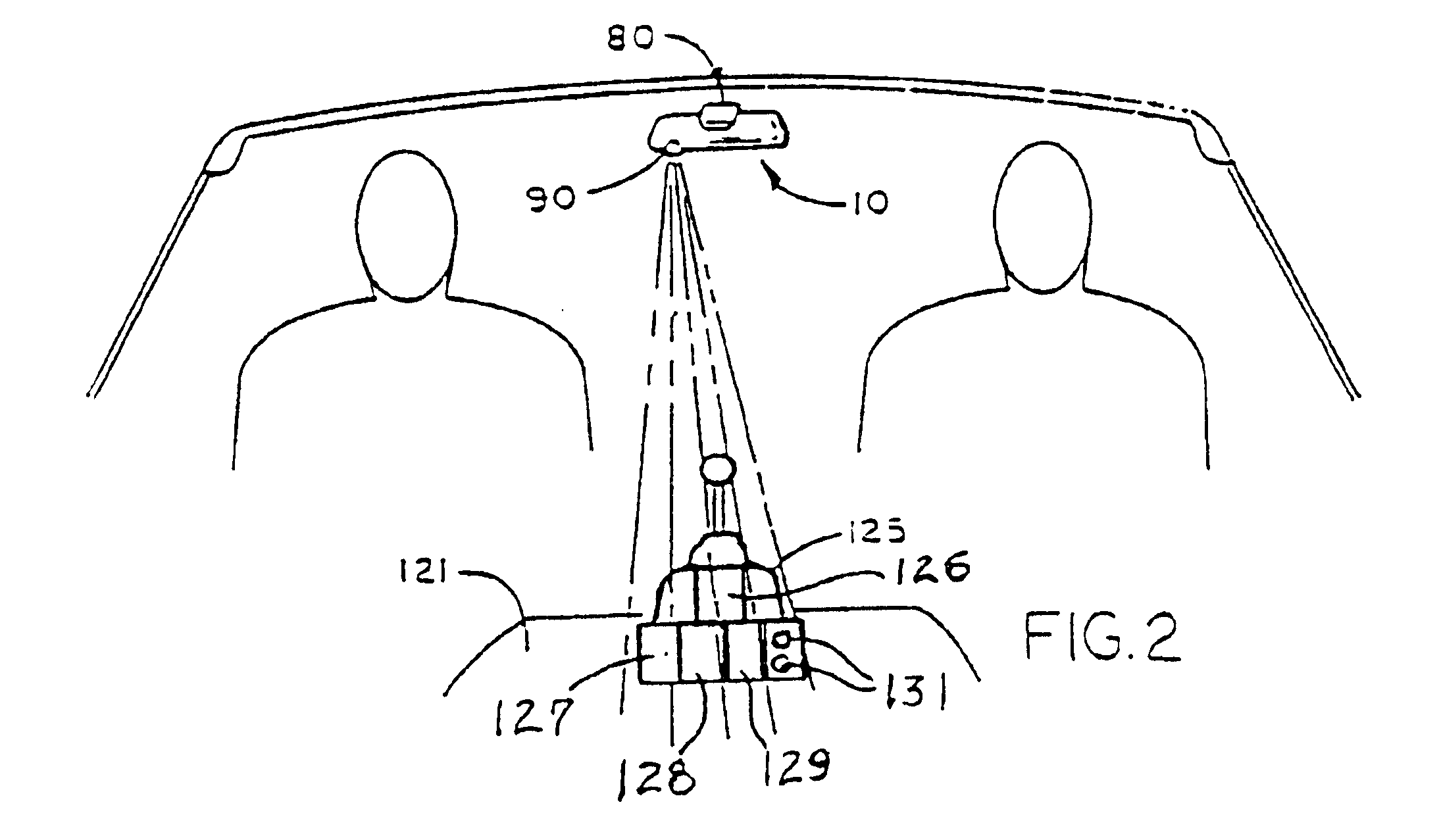
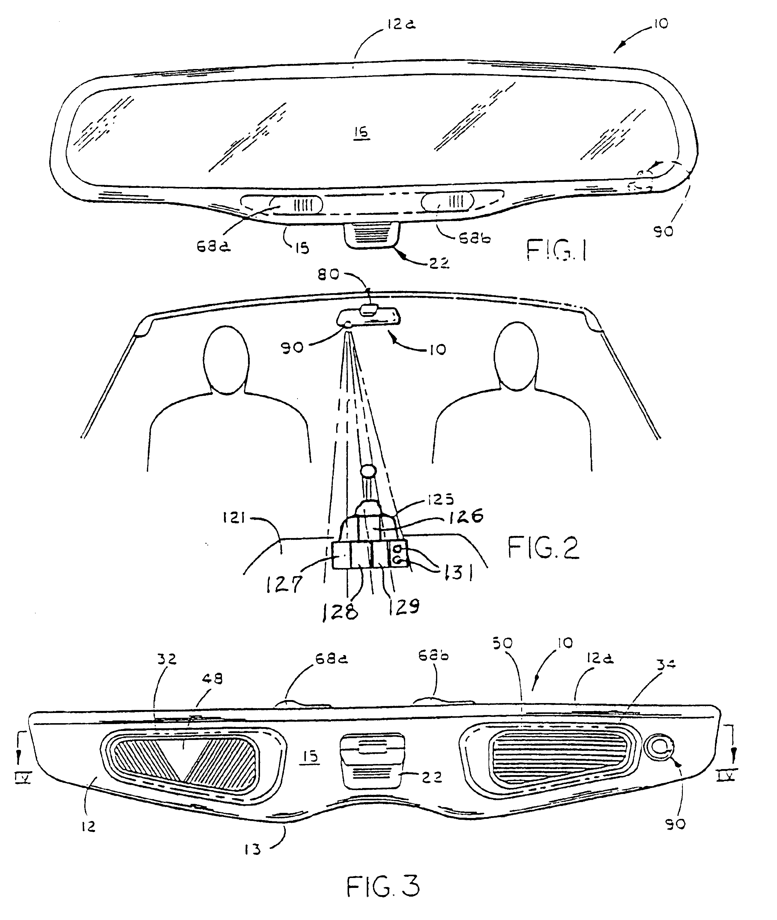
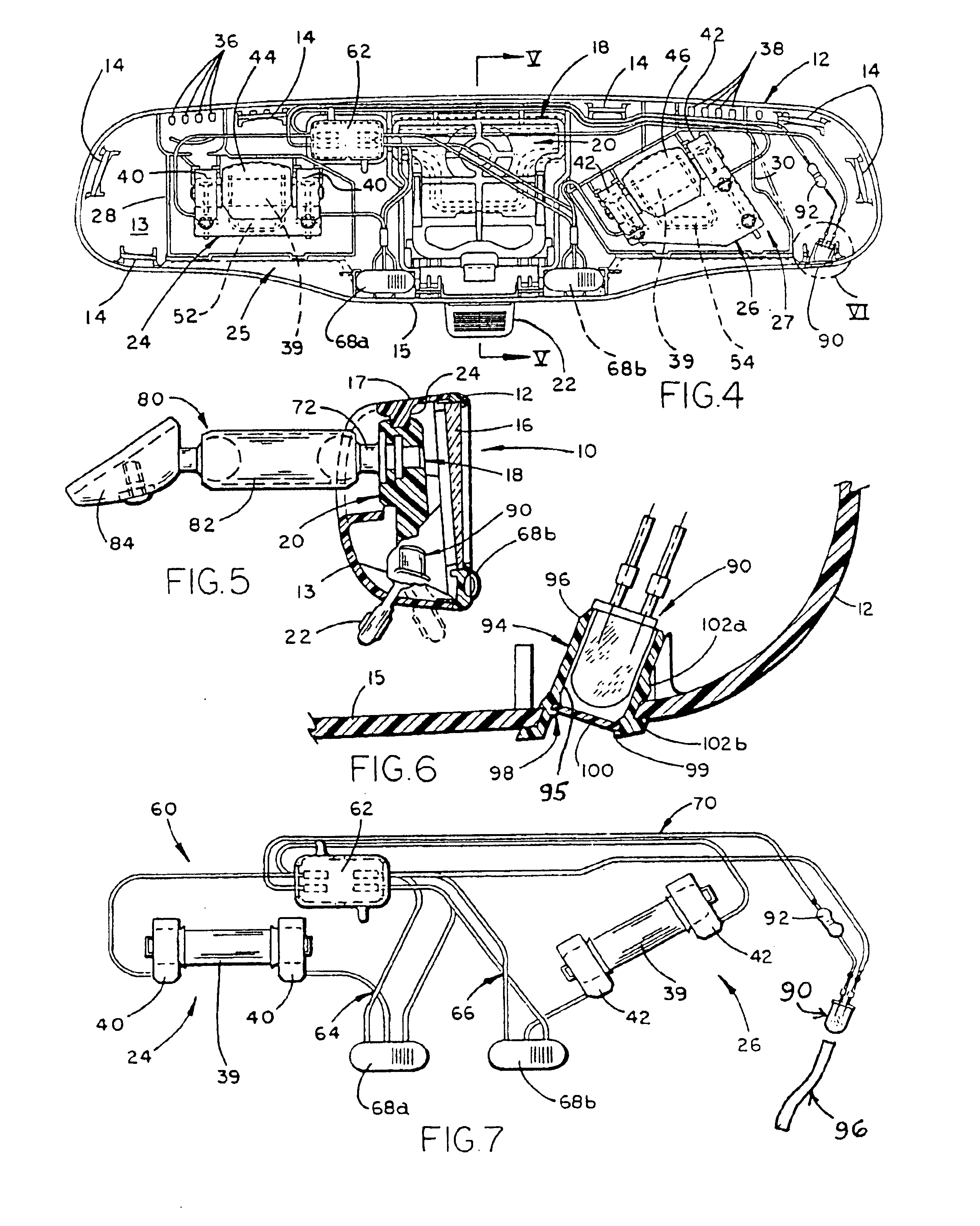
Referring now to the drawings in greater detail, FIGS. 1-7 illustrate a first embodiment 10 of an interior rearview mirror assembly of the present invention which incorporates a low level light emitting source adapted for centralized illumination of portions of a vehicle interior such as the instrumentation or controls in the instrument panel and / or console areas of a vehicle. Such console areas include floor consoles 121 (FIG. 2), shift lever consoles 125 (FIGS. 2 and 10), instrument panel consoles 130 (FIG. 10), side door consoles 134 (FIG. 10), and, for light emitting sources mounted to direct light upwardly to the roof areas of the vehicle, header consoles 136 (FIG. 10) located such as in the headliner area and roof area such as above the front vehicle seats. The shift lever console 125 includes the gear shift or transmission selector lever including the PRND21 transmission selector indicator panel 126 and, optionally, small part / coin storage bins 127, cup holders 128 ashtrays, ...


PUM


Abstract

Illumination of a portion of a vehicle interior is provided by an interior rearview mirror assembly incorporating a solid-state light source comprising a light emitting diode (LED) which emits light generally downwardly from the assembly. In one form of the invention, the mirror case of the rearview mirror assembly includes at least one of an opening, a light conduit, and a fiberoptic element through which the LED emits light. In another form, the LED preferably has a luminous intensity of at least 500 mcd when operated at a forward current of 20 mA. The LED preferably has a dominant wavelength of at least about 530 nm. The light emitted by the LED may be selected from green, orange, yellow, amber, reddish-orange, red and blue. The vehicle interior portion may include at least one of a shift lever console and a floor console.

Description

FIELD OF THE INVENTIONThis invention relates to interior vehicle instrumentation and / or console lighting and, more particularly, to interior rearview mirror assemblies and interior lamp assemblies for vehicles which incorporate a low level light emitting source for non-glare producing illumination of instrumentation or controls within a vehicle, especially in the instrument panel or control console areas at the front of the vehicle passenger compartment.BACKGROUND OF THE INVENTIONConventional lighting within vehicles includes general interior lighting for reading, entry of passengers at night and the like, as well as localized lighting for instrumentation and control switches. The former is typically provided by one or more lighting assemblies in the roof, header area, door panels or quarter window areas of the vehicle, while the latter is usually provided by means of individual light emitting sources at the rear of an instrument cluster or switch to provide back lighting visible fr...

Claims


Application Information

Patent Timeline
IPC IPC(8): B60Q3/02B60Q3/00
CPCB60Q3/001B60Q3/0293B60Q3/023Y10S362/80B60Q3/85B60Q3/258B60Q3/80
Inventor BOS, BRENT J.FORBES, STEPHEN J.VELDMAN, ROGER L.
Owner BOS BRENT J
Why Eureka
Eureka Blog
Learn More