Shock wave source with a wave damping coil carrier

a coil carrier and shock wave technology, applied in the field of shock wave sources, can solve the problems of unpleasant sound level of patients and medical personnel, audible waves arise, etc., and achieve the effects of reducing the formation of low-frequency waves, damping the propagation, and significantly reducing the generation of acoustic waves

Inactive Publication Date: 2005-02-01
SIEMENS AG
View PDF13 Cites 2 Cited by
  • Summary
  • Abstract
  • Description
  • Claims
  • Application Information

AI Technical Summary

Benefits of technology

In a further version of the invention, the material that damps the formation and / or the propagation of waves has a honeycomb structure. The material is plastic or resin-bonded paper according to one version of the invention. The honeycomb structure can be composed of regular and / or irregular polygons. A suitable material of plastic or resin-bonded paper having a honeycomb structure is distributed, for example, by Euro-Composites, Zone Industrielle, Luxemburg. A coil carrier that is fashioned of such a material having a honeycomb structure also noticeably reduces the formation of low-frequency waves and noticeably damps the propagation of low-frequency and high-frequency waves. As a result the generation of acoustic waves is significantly reduced when generating shock waves.
In another embodiment of the invention the coil carrier has a longitudinal axis, and the coil carrier is fashioned such that a cross-sectional area of the coil carrier intersected at a right angle by its longitudinal axis has a non-circular contour. Inventively, this represents a rejection of a high degree of symmetry of the coil carrier. This said high degree of symmetry contributes to the disadvantage that radial or plate waves forming during the course of generating shock waves and superimposing equiphase due to reflection at the edge surfaces of the coil carrier, resulting in acoustic waves having a higher sound level being generated. By departing from this high degree of symmetry, the equiphase superimposition of, in particular, radial waves and plate waves is at least reduced, so that the generation of acoustic waves with a high sound level also is reduced.

Problems solved by technology

As a result, audible waves arise that have a very unpleasant sound level for patients and medical personnel.

Method used


Image

  • Shock wave source with a wave damping coil carrier
  • Shock wave source with a wave damping coil carrier
  • Shock wave source with a wave damping coil carrier

Examples


Embodiment Construction

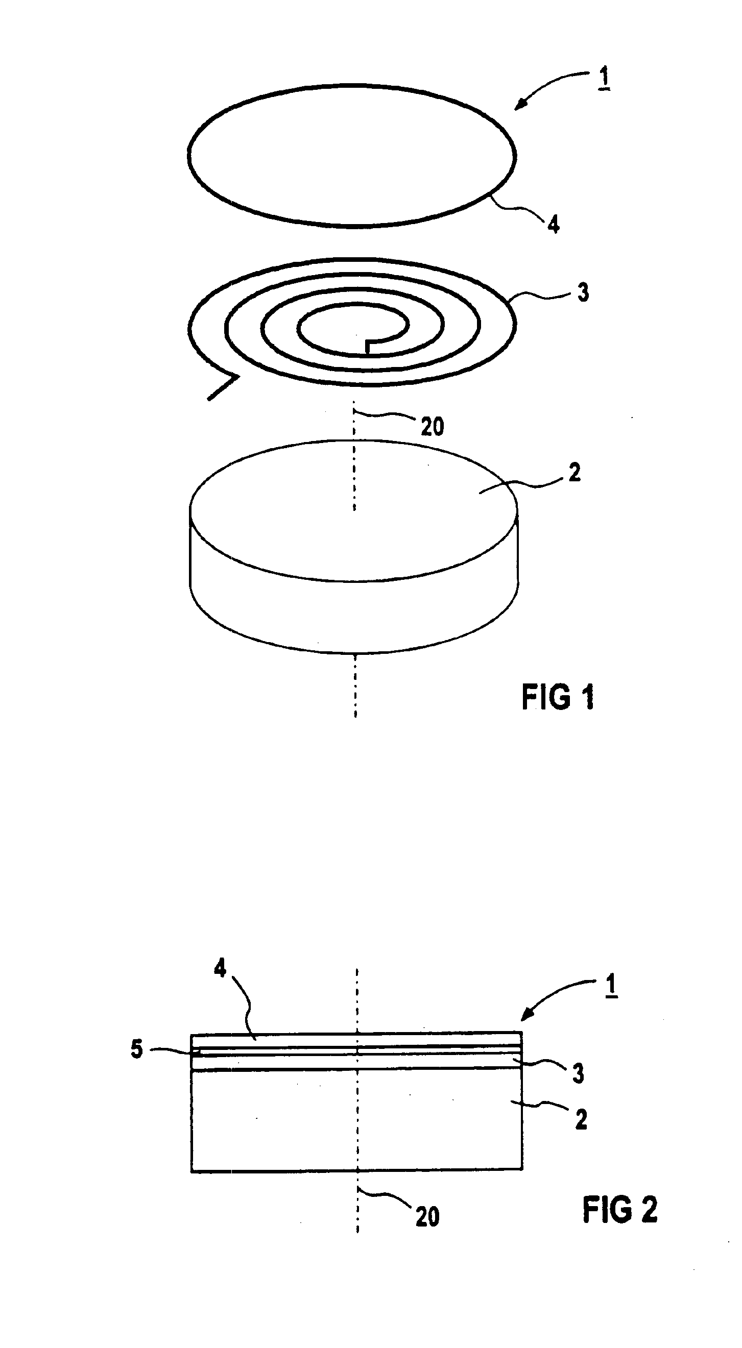
FIG. 1 shows a highly schematic illustration of the components of a known electromagnetic shock wave source 1. In the exemplary embodiment, the shock wave source 1 has a disk-shaped coil carrier 2, a flat coil 3 and a metallic membrane 4. For illustrating the structure of the shock wave source 1, the coil carrier 2, the flat coil 3 and the membrane 4 are shown separated in FIG. 1. In the operational state of the shock wave source 1 shown in FIG. 2, the flat coil 3 lies on the coil carrier 2 and is separated from the metallic membrane 4 in insulating fashion by an insulating foil 5 (not shown in FIG. 1). When generating shock waves, a brief-duration high-voltage pulse is applied to the flat coil 3 arranged on the coil carrier 2. Due to the electromagnetic interaction of the flat coil 3 with the membrane 4 separated therefrom in insulating fashion, this is repelled into an acoustic propagation medium (not explicitly shown in FIGS. 1 and 2), which is usually water. A shock wave is gene...


PUM


Abstract

A shock wave source has a coil carrier, a coil, having a metallic membrane separated from the coil in insulating fashion for generating shock waves. The coil carrier is formed of a material that damps the formation and/or the propagation of audible acoustic waves in the generation of shock waves.

Description

BACKGROUND OF THE INVENTION1. Field of the InventionThe present invention is directed to a shock wave source of the type having a coil carrier, a coil and a metallic membrane separated from the coil in insulating fashion for generating shock waves.2. Description of the Prior ArtElectromagnetic shock wave sources of the type described above are utilized, for example, in medicine for the non-invasive disintegration of body calculi of a patient, for example for the disintegration of kidney stones. The generation of shock waves with such a shock wave source is accomplished by a brief-duration high-voltage pulse applied to the coil arranged on the coil carrier. As a result of the electromagnetic interaction of the coil with the metallic membrane separated from it in insulating fashion, the membrane is repelled from the coil in an enclosed volume of water located between the shock wave source and the patient. As a result, attenuated sine waves are emitted into the water as carrier medium ...

Claims


Application Information

Patent Timeline
Patent Type & Authority Patents(United States)
IPC IPC(8): A61B17/22B06B1/02B06B1/04G10K15/04G10K11/16G10K11/00
CPCA61B17/22004A61B17/2251G10K15/043B06B1/045G10K11/16A61B2017/22027
Inventor BECHTOLD, MARIOFEHRE, JENSGRANZ, BERNDMAHLER, MATTHIAS
Owner SIEMENS AG
Why Eureka
Try Eureka