Image transfer sheet with transfer blocking overcoat and heat transfer process using the same

a technology of image transfer and heat transfer process, which is applied in the direction of transportation and packaging, thermography, synthetic resin layered products, etc., can solve the problems of reducing the esthetic appeal of the transfer image, the image prepared by conventional screen printing followed by dry heat transfer to a cloth substrate is often cracked and peeling from the substrate with repeated laundering, and the effect of cost saving

Inactive Publication Date: 2005-02-01
SCHWENDIMANN JODI
View PDF7 Cites 53 Cited by
  • Summary
  • Abstract
  • Description
  • Claims
  • Application Information

AI Technical Summary

Benefits of technology

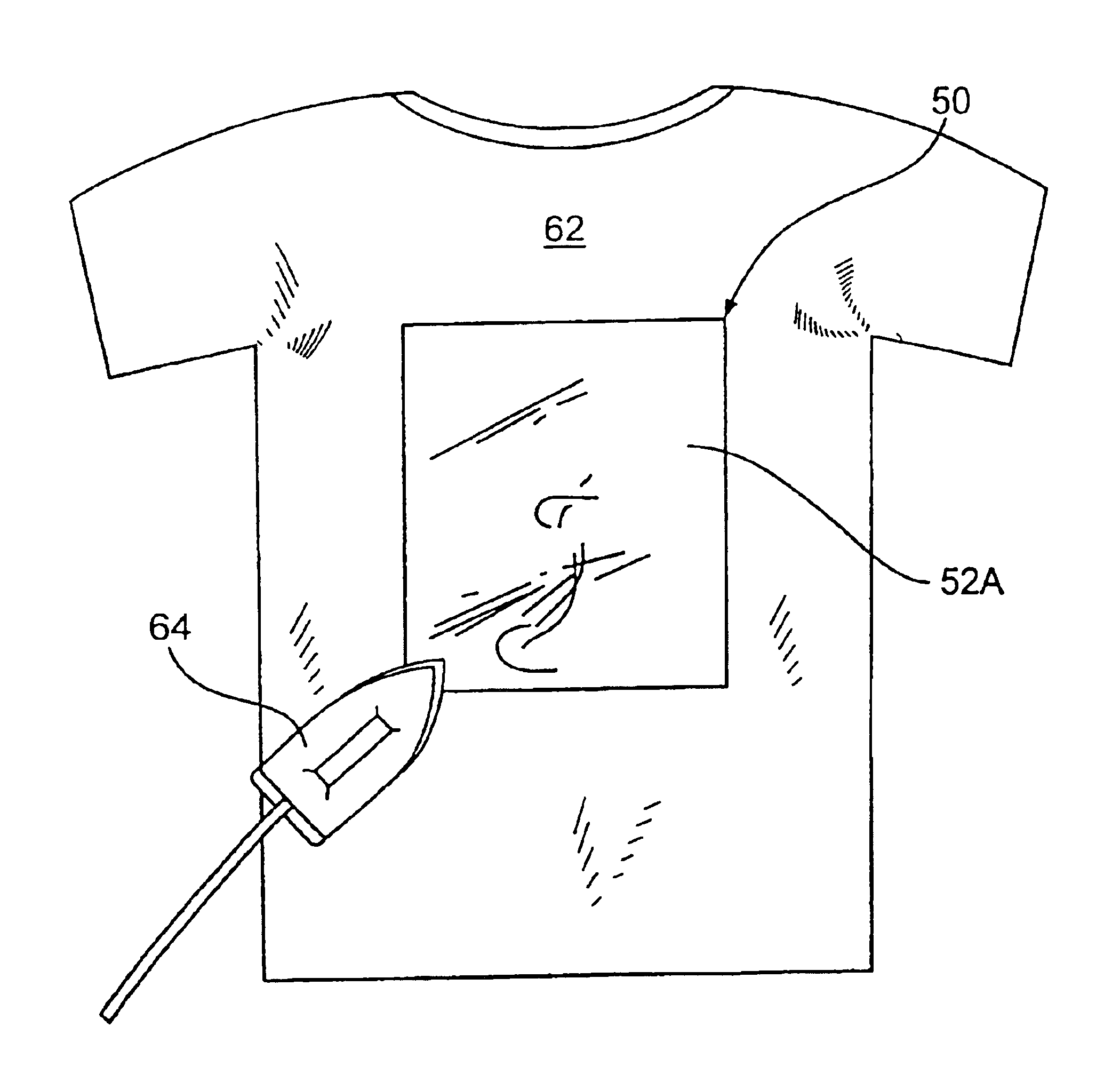
In order to attract the interest of consumer groups that are already captivated by the tee shirt rage described above, the present invention provides, in one embodiment, an improved transfer sheet. In another embodiment, the present invention provides for a process of dry heat transfer of images to receptors. A unique advantage of the present invention is that it allows for the reduction of the polymer halo around the transferred image. The present invention also provides for the “hand” or feel of the substrate after transferring. Furthermore, the transfer process of the present invention can be effected by the use of a conventional hand iron. Thus, the present invention enables all consumers to wear and display apparel carrying designs that were formed on the transfer material and by the process of the present invention in a timely and cost efficient means.
is that it allows for the reduction of the polymer halo around the transferred image. The present invention also provides for the “hand” or feel of the substrate after transferring. Furthermore, the transfer process of the present invention can be effected by the use of a conventional hand iron. Thus, the present invention enables all consumers to wear and display apparel carrying designs that were formed on the transfer material and by the process of the present invention in a timely and cost efficient means.
Accordingly, the present invention relates to a transfer transferable material and a process for offset printing of a heat transferable material having a transfer blocking overcoat.
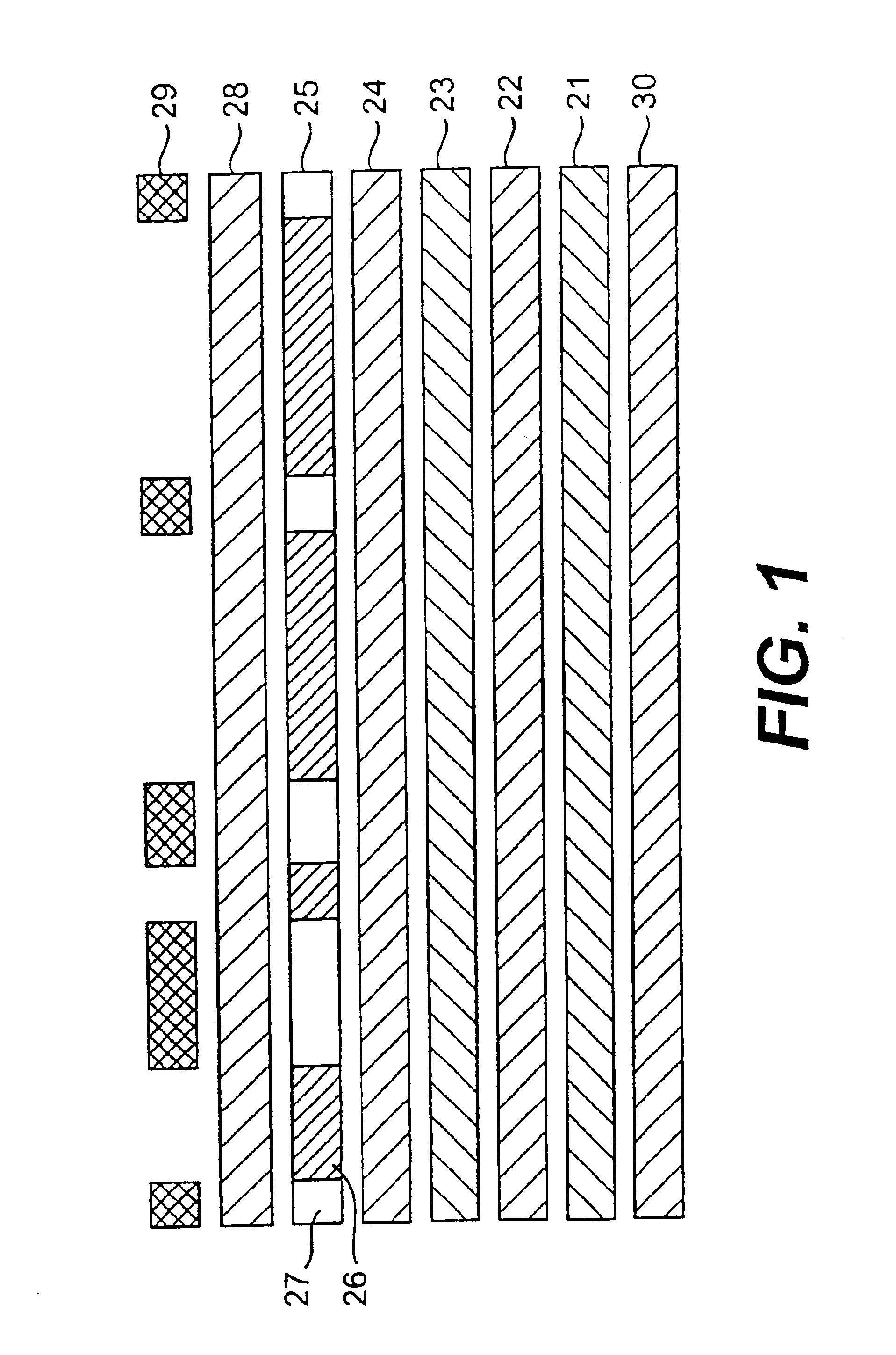
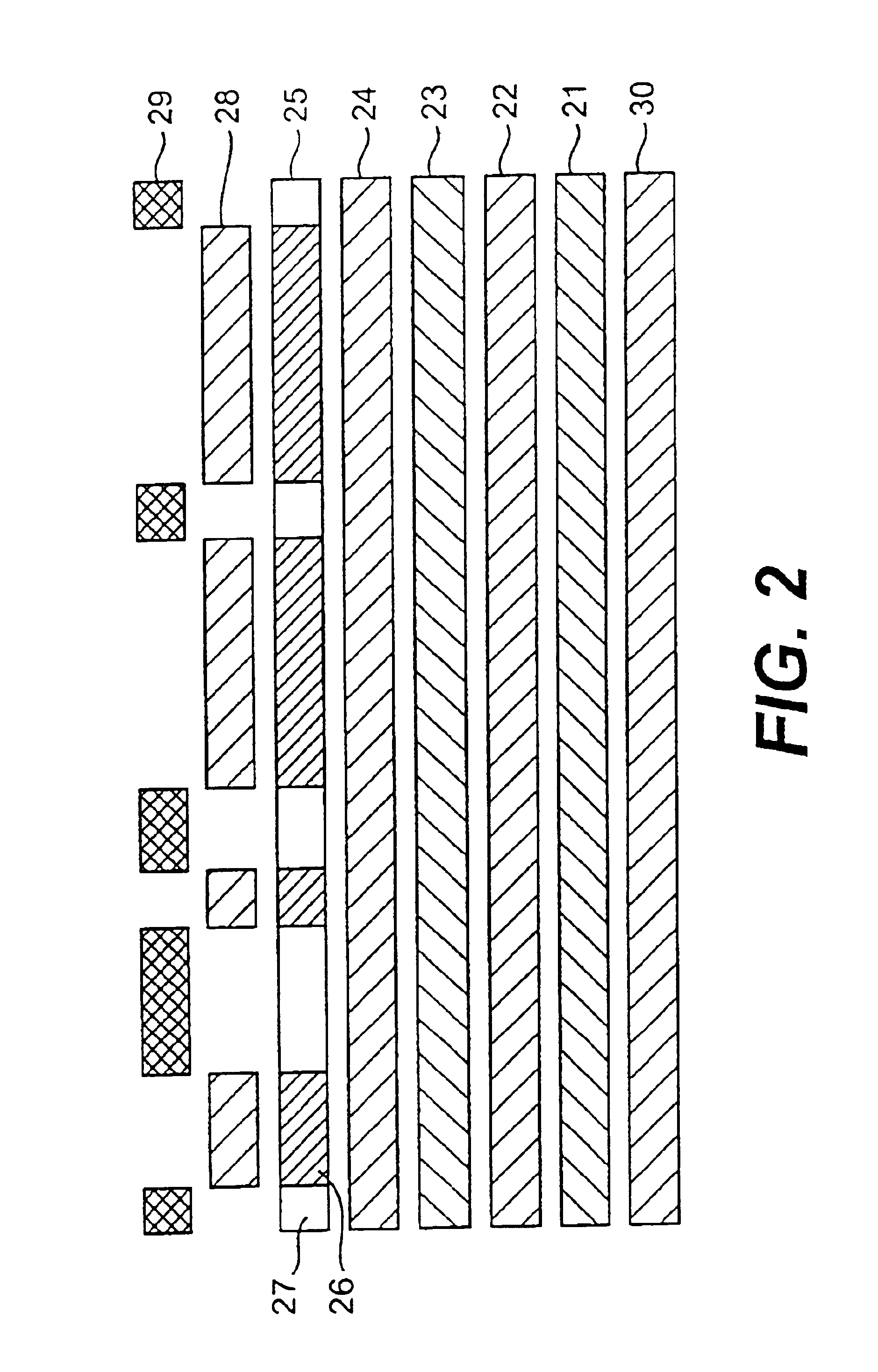
In one embodiment, the present invention provides for a transfer sheet comprising a support, a heat release polymer layer, a design layer containing image and non-image areas, and a transfer blocking overcoat layer, wherein the transfer blocking overcoat layer is applied on top of non-image areas only.
In another embodiment, the present invention provides for a transfer sheet comprising a support, a heat release polymer layer on one side of the support, a design layer containing image and non-image areas on top of the heat release polymer layer, a polymer layer containing a clear or colored non-water dispersible polymer on top of the design layer, and a transfer blocking overcoat layer, wherein the transfer blocking overcoat layer is applied on top of non-image areas only.
In another embodiment, the present invention provides for a transfer sheet comprising a support, a heat release polymer layer on one side of the support, an layer containing image and non-image areas on top of the heat release polymer layer, a polymer layer containing a clear or colored non-water dispersible polymer, and a transfer blocking overcoat layer, wherein the polymer layer containing a clear or colored non-water dispersible polymer is applied on top of the image areas only, and the transfer blocking overcoat layer is applied on top of the non-image areas only.

Problems solved by technology

One problem with many known transfer sheets is the loss of “hand” or the formation of hard or brittle images on the substrate.
Over time, these image layers crack, chip and peel from the substrate resulting in a reduction in the esthetic appeal of the transfer image.
For example, images prepared by conventional screen printing followed by dry heat transfer to a cloth substrate frequently crack and peel from the substrate with repeated laundering.
Although these processes minimize the polymer halo, the transferred image remains susceptible to cracking and peeling.
This method also, however, does not prevent the transferred image from cracking and peeling.
However, there were several drawbacks to the process of U.S. Pat. No. 5,741,387.
First, the problem of cracking, chipping and peeling of the image layers over time still existed.
Second, the application of the image layer to the substrate required a considerable amount of pressure.
Accordingly, there continue to exist problems associated with clearly transferring an image to a substrate and providing for the “hand” or feel of the substrate after the image has been transferred.

Method used


Image

  • Image transfer sheet with transfer blocking overcoat and heat transfer process using the same
  • Image transfer sheet with transfer blocking overcoat and heat transfer process using the same
  • Image transfer sheet with transfer blocking overcoat and heat transfer process using the same

Examples


example 1

In one embodiment of the invention, the barrier layer is a vinyl acetate polymer. An example of this embodiment is Barrier Layer Formulation 1:

Barrier Layer Formulation 1ComponentsPartsVinyl acetate-dibutyl maleate50 partspolymer dispersion (such asEVERFLEX G, Hampshire ChemicalCorporation)Water50 parts.

Barrier Layer Formulation 1 may be prepared as follows: fifty parts of a vinyl acetate-dibutyl maleate polymer dispersion are combined with fifty parts of water by gentle stirring. The stirring is continued for approximately ten minutes at a moderate stir rate (up to but not exceeding a rate where cavitation occurs). The amount of water added may vary. The only limitation is that sufficient water is added to make the dispersion coatable on the substrate.

example 2

An example of the PMMA-containing barrier layer is Barrier Layer Formulation 2:

Barrier Layer Formulation 2ComponentsPartsAcetone40 parts (weight)99.5%2-Propanol40 parts (weight)99.5%PMMA20 parts (weight).

Barrier Layer Formulation 2 may be prepared as follows: The acetone and 2-propanol are weighed and mixed. The mixture is stirred. One half of the PMMA is added to the mixture while the mixture is heated to about 25° C. and stirring continues until the PMMA is dispersed. At this point, stirring continues until the remainder of the PMMA is added to the mixture and is dispersed. The mixture is then allowed to cool to room temperature.

example 3

This example relates to a release layer formulation. This is referred to as Release Layer Formulation 1:

Release Layer Formulation 1ComponentsParts by weightEthylene Acrylic Acid86partsCo-polymer Dispersion(Michem Prime 4983R, Michelman)Elastomeric emulsion5parts(Hystretch V-29, B F Goodrich)Polyurethane Dispersion (Daotan4partsVTW 1265, Vianova Resins)Polyethylene Glycol (Carbowax4partsPolyethylene Glycol 400,Union Carbide)Polyethylene Glycol Mono1part((Tetramethylbutyl) Phenol)Ether (Triton X-100, UnionCarbide)

Release Layer Formulation 1, as an embodiment of the invention suitable for laser copiers and laser printers, is wax free. Release Layer Formulation 1 may be prepared as follows: five parts of the elastomer dispersion are combined with eighty-six parts of an ethylene acrylic acid co-polymers dispersion by gentle stirring to avoid cavitation. Four parts of a polyurethane dispersion are then added to the mixture. Immediately following the addition of a polyurethane dispersion, ...


PUM

PropertyMeasurementUnit
pressureaaaaaaaaaa
temperatureaaaaaaaaaa
pressureaaaaaaaaaa

Abstract

An image transfer sheet, having a support sheet, an optional barrier layer on the support sheet, a heat release layer on the optional barrier layer or on the support sheet, an optional image-receiving layer on the heat release layer, a design layer having image and non-image areas on the optional image-receiving layer on the heat release layer, an optional non-water-dispersible polymer layer on the design layer, and a transfer blocking overcoat layer on the optional polymer layer or the design layer, is used in a dry heat transfer process to transfer an image area to a receptor.

Description

BACKGROUND OF THE INVENTION1. Field of the InventionThe present invention relates to a transfer material and process for offset printing of a heat transferable material having a transfer blocking overcoat.2. Description of the Prior ArtTextiles such as shirts (e.g., tee shirts) having a variety of designs thereon have become very popular in recent years. Many shirts are sold with pre-printed designs to suit the tastes of consumers. In addition, many customized tee shirt stores are now in the business of permitting customers to select designs or decals of their choice. Processes have also been proposed which permit customers to create their own designs on transfer sheets for application to tee shirts by use of a conventional hand iron, such as described in U.S. Pat. No. 4,244,358 issued Sep. 23, 1980. Furthermore, U.S. Pat. No. 4,773,953 issued Sep. 27, 1988, is directed to a method for utilizing a personal computer, a video camera or the like to create graphics, images, or creative ...

Claims


Application Information

Patent Timeline
Patent Type & Authority Patents(United States)
IPC IPC(8): D06Q1/12D06Q1/00B44C1/17
CPCD06Q1/12B44C1/1729Y10T428/31551Y10T428/31786Y10T428/31855
Inventor WILLIAMS, SCOTT A.
Owner SCHWENDIMANN JODI
Why Eureka
Try Eureka