TDMA transmit frequency generator suppressing frequency jumps caused by feedback

a technology of transmit frequency and feedback, applied in the direction of pulse generator, pulse manipulation, pulse technique, etc., can solve the problems of large effect, undesired frequency jump generation, and disruption of frequency generation, and achieve the effect of high integration density of circuits and cost-effective manufactur

Inactive Publication Date: 2005-02-01
SIEMENS AG
View PDF6 Cites 7 Cited by
  • Summary
  • Abstract
  • Description
  • Claims
  • Application Information

AI Technical Summary

Benefits of technology

The object of the invention is therefore to disclose an electronic circuit for generating a transmission frequency which on the one hand offers the favorable technical requirements of the transmission mixing concept and on the other hand permits a high integration density of the circuit to be achieved, and thus makes cost-effective manufacture possible.

Problems solved by technology

The problem of such a simple circuit is that the generation of frequencies is disrupted at the moment of the switching on of the transmit amplifier owing to the load change in the amplifier or due to feedback.
As a result, an undesired frequency jump is generated.
In particular in TDMA systems which, for costs reasons, operate with a slow PLL control loop, or open the control loop for the duration of the modulation, this effect is a large problem for the implementation because the frequency jump can no longer be corrected by the PLL circuit.
The greatest disadvantage of this transmission mixing concept is the large degree of technical expenditure which it requires because a transmission mixer stage, an oscillator including a PLL circuit for frequency stabilization and a band filter are additionally required.
The additionally required electronic components alone result in a considerable cost disadvantage in comparison with the two preceding solutions.
A further disadvantage of this more costly transmission mixing concept is that the overall size of such a circuit is too large owing to the number of additional electronic components.
In this transmission mixing concept, it proves particularly difficult to achieve a high degree of integration because given the current state of the art the filters and oscillators or oscillator coils are very difficult to accommodate in integrated circuits, or require a very large chip area.
In addition, it is frequently impossible to integrate to a sufficient degree the capacitors and resistors which are required for the PLL so that they have to be arranged as external components.
Because a total of two oscillators for frequency stabilization, two PLLs, including two external loop filters, are necessary in the known transmission mixing concept, and in particular oscillators with a low frequency require a particularly large chip area or have poor properties with respect to phase noise, this transmission mixing concept proves relatively unsuitable for a high integration density.

Method used


Image

  • TDMA transmit frequency generator suppressing frequency jumps caused by feedback
  • TDMA transmit frequency generator suppressing frequency jumps caused by feedback
  • TDMA transmit frequency generator suppressing frequency jumps caused by feedback

Examples


Embodiment Construction

Reference will now be made in detail to the preferred embodiments of the present invention, examples of which are illustrated in the accompanying drawings, wherein like reference numerals refer to like elements throughout.

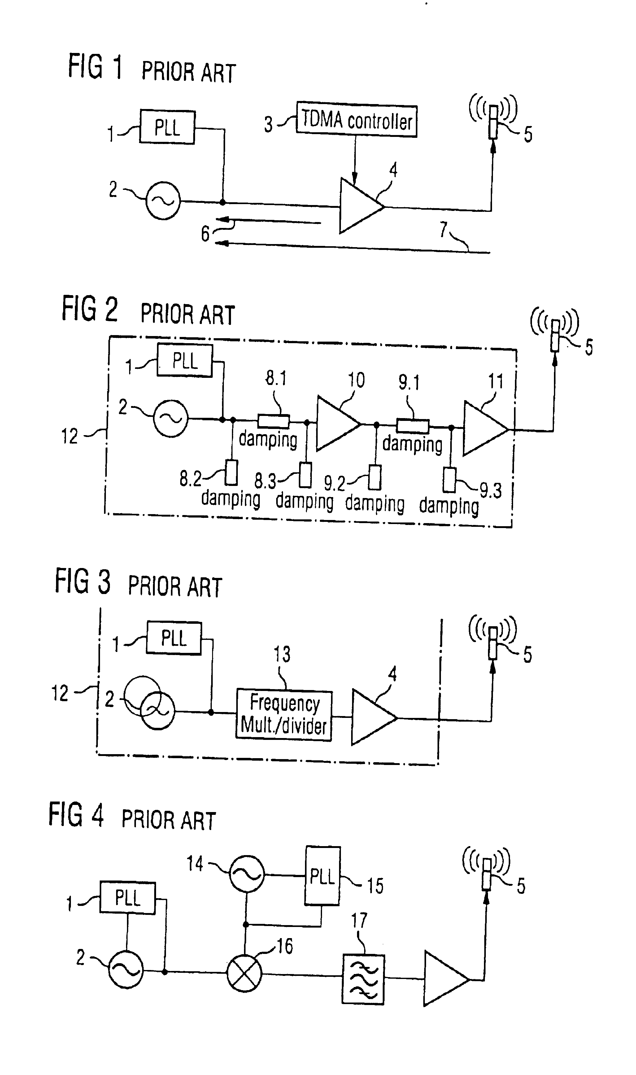
FIG. 1 shows a known circuit for a TDMA radio system with an oscillator 2 and a PLL circuit 1 for generating a frequency which is as stable as possible, a TDMA controller 3 of a transmitting amplifier 4 and an antenna 5.

In this circuit, at the moment of the switching on of the transmitting amplifier 4, the generation of frequencies is disrupted owing to a load change and / or effects—indicated by the arrows 6 and 7—and an undesired frequency jump is produced. The load change occurs during the switching on of the transmitting amplifier 4 as a result of the change in its input impedance.

Effects on the frequency generating components are produced as a result of the irradiation by the antenna 5, or by other coupling paths (not illustrated here) between the transmit outpu...


PUM


Abstract

A transmit frequency is generated for a transceiver by a controllable oscillator which generates an oscillator frequency, a divider by a factor N, and a mixer stage with a subsequent band filter. Signals with the oscillator frequency and the oscillator frequency divided by the factor N are to the mixer stage to generate an output signal at the transmit frequency.

Description

CROSS REFERENCE TO RELATED APPLICATIONSThis application is based on and hereby claims priority to German Patent Application No. 19928998 filed on Jun. 24, 1999, the contents of which are hereby incorporated by reference.BACKGROUND OF THE INVENTION1. Field of the InventionThe invention relates to an electronic circuit for generating a transmit frequency for a transceiver.2. Description of the Related ArtThe inventors are familiar with similar circuits from the prior art for generating corresponding transmit frequencies in a TDMA radio system (for example DECT, GSM, PHS). The abbreviation TDMA stands for “Time Division Multiple Access”. A typical circuit is composed of an oscillator for generating frequencies, a transmit amplifier, a receiver and a control device which determines the chronological sequence of alternating transmit and receive states. In general, the oscillator frequency for setting the transmission channel via the control device using a PLL (phase locked loop) is set b...

Claims


Application Information

Patent Timeline
Patent Type & Authority Patents(United States)
IPC IPC(8): H03L7/185H03L7/16H03B21/02H03B21/00H04B1/04
CPCH03B21/02H03L7/185H03L7/16H04B1/40
Inventor DETERING, VOLKERHEINEN, STEFAN
Owner SIEMENS AG
Why Eureka
Try Eureka