Controller for a laser using predictive models of materials processing

a technology of predictive models and lasers, applied in the direction of electric programme control, program control, instruments, etc., can solve the problems of affecting the accuracy and quality of the process, affecting the dynamic position and velocity errors of the physical system, and certain non-wrong characteristics

Inactive Publication Date: 2005-02-01
LASX INDS
View PDF11 Cites 26 Cited by
  • Summary
  • Abstract
  • Description
  • Claims
  • Application Information

AI Technical Summary

Benefits of technology

[0007]The present system recognizes that even though the sensors may not be sufficiently accurate to monitor certain fast operations, the system may act in a repeatable way. Any physical system may have dynamic posit

Problems solved by technology

Any physical system may have dynamic position and velocity errors that effect the accuracy and quality of the process.
There are

Method used


Image

  • Controller for a laser using predictive models of materials processing
  • Controller for a laser using predictive models of materials processing
  • Controller for a laser using predictive models of materials processing

Examples


Embodiment Construction

ystem;

[0019]FIG. 7D shows a constant energy density control function;

[0020]FIGS. 7E and 7H each show control functions for variable energy density;

[0021]FIGS. 7F and 7G show the energy density control function energy pass response;

[0022]FIGS. 8A and 8B show operation of laser power control using an energy density model;

[0023]FIGS. 9A-9G show an example using controlled depth cutting,

[0024]FIGS. 10A and 10B show position based perforation;

[0025]FIGS. 11A and 11B show operations for grayscale scribing;

[0026]FIGS. 12A-12C show in position control function for sharp corner response.

DETAILED DESCRIPTION

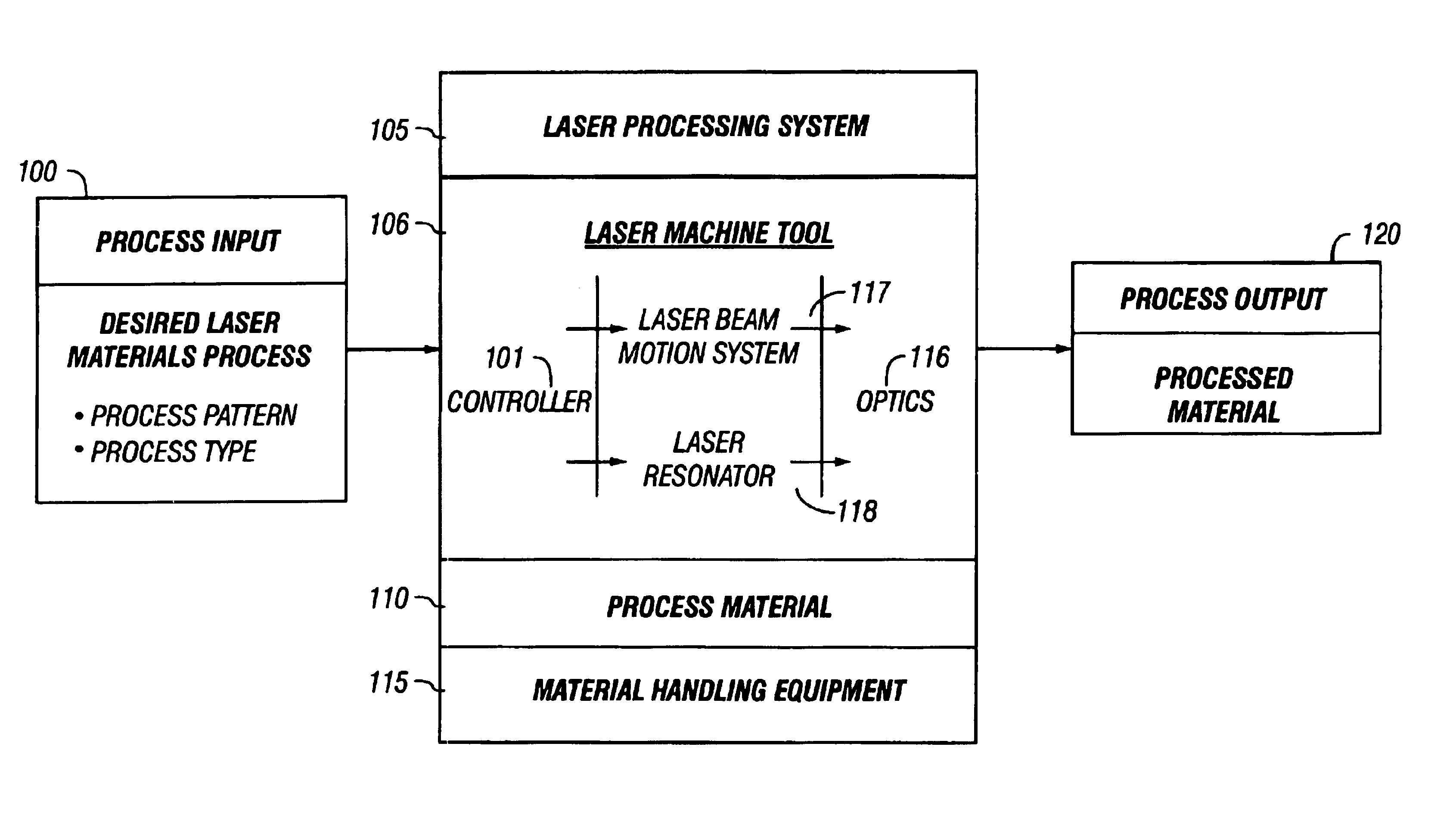
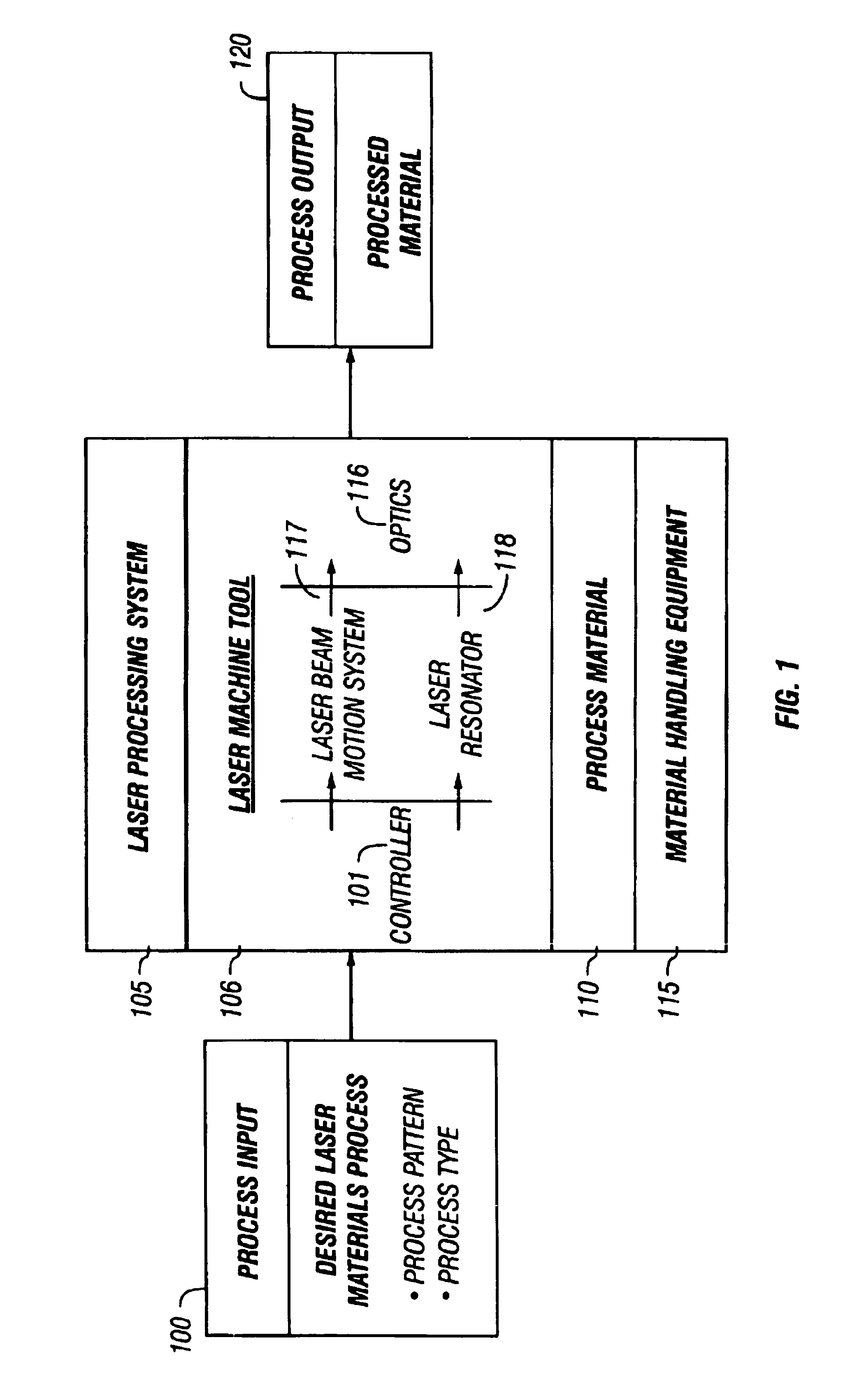
[0027]A block diagram of the overall system is shown in FIG. 1. Process input 100 may include the parameters which define the kind of process material and pattern that is going to be formed. For example, the process input may include the “process pattern”, which may be a computer file that represents the patterns to be formed on the material. It may also include “process type” which indica...


PUM

PropertyMeasurementUnit
Poweraaaaaaaaaa
Inertiaaaaaaaaaaa
Erroraaaaaaaaaa

Abstract

Predictive models of physical parts of the laser processing system part determined. These predictive models are used to determine how the physical system will actually react. The predicted reaction from the models is used as feedback in order to produce the control signals. These physical models therefore adjust to the operation of the system, much in the way that actual feedback would adjust the operation of the system. However, the system may be used at faster speeds, where the actual feedback could not be produced fast enough. Different kinds of modeling are described, including in-position feedback which models sharp movements of the laser system, trajectory models which superimpose the commanded curve over the predicted actual curve to determine errors in trajectory, and constant/variable energy density controls.

Description

CROSS REFERENCE TO RELATED APPLICATIONS[0002]This application claims benefit of U.S. Provisional Application No. 60 / 280,270, filed Mar. 29, 2001.BACKGROUND OF INVENTION[0003]Modern numerically controlled laser elements, and other machine controlled laser elements, may process materials at very high rates. The process velocity may be defined as the relative velocity that exists between the laser beam and the material being processed. It is desirable to make sure that the laser is processing the material in the desired way.[0004]However, the state-of-the-art of monitoring devices may not be able to accurately monitor such processes at these high process velocities. The sensors or feedback elements that currently exist are not sufficiently accurate to monitor these operations. Accordingly, prior art devices have often used highly trained technicians to set up and operate the process. These highly trained technicians are often very expensive. Even when such highly trained technicians ar...

Claims


Application Information

Patent Timeline
IPC IPC(8): B23K26/04G06F17/00G06F19/00B23K26/00B23K26/08G05B13/04G05B17/00G05B17/02G05B19/19
CPCB23K26/08B23K26/0807G05B19/19G05B13/048G05B2219/45165G05B2219/42058B23K26/082
Inventor DINAUER, WILLIAM R.WEIGMAN, THOMAS V.
Owner LASX INDS
Why Eureka
Try Eureka