Mixing method, mixing structure, micromixer and microchip having the mixing structure

a technology of mixing structure and mixing method, which is applied in the field of mixing structure, can solve the problems of liquid viscosity, liquid cannot be moved easily, and the micromixing structure is not disclosed, so as to achieve the effect of diffusing mixing

Inactive Publication Date: 2005-02-08
MINOLTA CO LTD
View PDF9 Cites 28 Cited by
  • Summary
  • Abstract
  • Description
  • Claims
  • Application Information

AI Technical Summary

Benefits of technology

Therefore, a technical problem to be solved by the present invention is to provide a mixing method, a mixing structure, a micromixer and a microchip having the mixing structure which are capable of carrying out diffuse mixing in a microarea efficiently. Hereinafter, “mixing” may include not only mixing a plurality of liquids or fluids but also extracting substances such as particles from a first liquid or fluid to a second liquid or fluid.

Problems solved by technology

However, it does not disclose a micromixing structure in which a plurality of branched flow passes are arranged three-dimensionally and are interflowed in parallel.
Meanwhile, in a current macroscale apparatus, turbulent mixing according to the mechanical system is generally carried out by using a test tube or the like with diameter of about 5 mm, but the apparent viscosity of a liquid abruptly increases by influences of capillary force and resistance of a flow pass in microscale in comparison with the macroscale, and thus the liquid does not move easily.
However, when the width of the flow pass is reduced to an extreme in order to quicken the diffuse time efficiently, the resistance of the flow pass becomes extremely large.
As a result, the feeding of the liquid cannot be controlled and also very high pressure is required for feeding the liquid.
For this reason, the liquid feeding mechanism is enlarged, and thus a microsystem cannot be established entirely.
Moreover, when the width of the flow pass is extremely small, an amount of the liquid is extremely small.
As a result, the detection limit is lowered and a higher-sensitive detection mechanism is required, and applications are limited in the current direction method.

Method used


Image

  • Mixing method, mixing structure, micromixer and microchip having the mixing structure
  • Mixing method, mixing structure, micromixer and microchip having the mixing structure
  • Mixing method, mixing structure, micromixer and microchip having the mixing structure

Examples


first embodiment

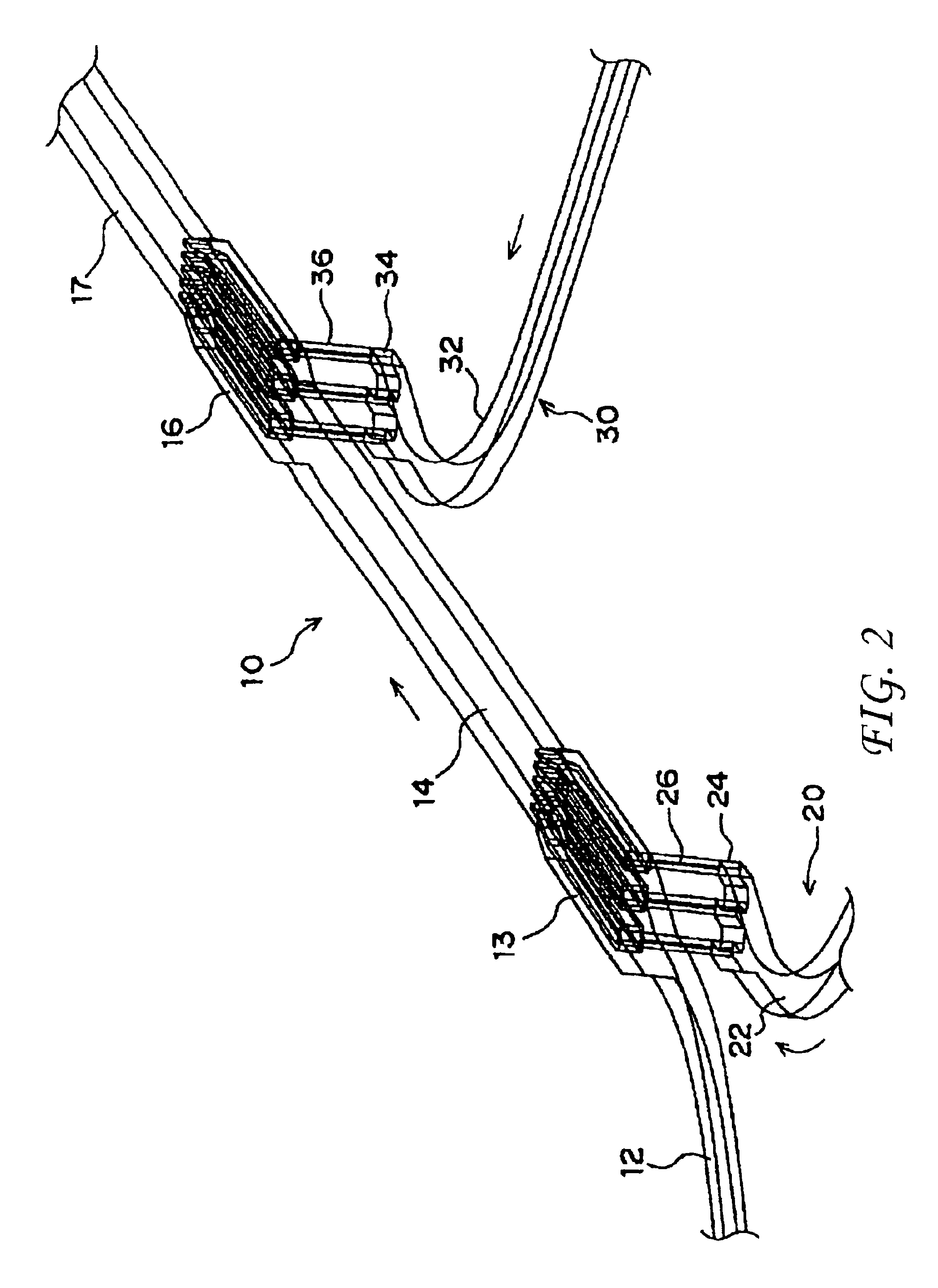
Firstly, there will be explained below the present invention with reference to FIGS. 2 to 10. FIGS. 2 to 10 show embodiments of a microchip 2 to be used for testing blood coagulation.

As shown in FIG. 2, in the microchip 2, three flow pass sections 10, 20 and 30 are constituted three-dimensionally. Connection flow passes 26 and 36 which are connected to the second flow pass section 20 and the third flow pass section 30 respectively interflow with first and second interflow sections 13 and 16 from the bottom. The first and second interflow sections 13 and 16 are provided in the middle of the first flow pass section 10 through which a specimen (blood) is flowed. A diluent is flowed through the second flow pass section 20. A reagent is flowed through the third flow pass section 30. The respective liquids are mixed in first and second mixing flow passes 14 and 17 on the lower stream side. An end of a lower portion 22 of the second flow pass section 20 is branched into three, and the thre...

second embodiment

There will be explained below the present invention with reference to FIG. 11.

As for a microchip 3, three flow pass sections 62, 64 and 66 are formed on a substrate 60. The first and second flow pass sections 62 and 64 interflow with the third flow pass section 66 in the substrate 60. Openings 62a and 66a which are one ends of the first and third flow pass sections 62 and 66 are formed on the upper surface of the substrate 60. An opening 64a which is one end of the second flow pass section 64 is formed on the lower surface of the substrate 60. Two liquids supplied from the openings 62a and 64a interflow in the third flow pass section 66 and are discharged from the opening 66a.

The respective flow pass sections 62, 64 and 66 extend to the approximately same direction in a vicinity portion of the joint portion of the flow pass sections 62, 64 and 66 so that the least disturbance and deflection occur in the liquids when the liquids interflow. Dimensions of the flow pass sections 62, 64...

embodiment 1

As shown by a dotted line in FIG. 11(a), for example, a section decreased portion 67 of which depth becomes smaller gradually is provided in the third flow pass section 66 similarly to the embodiment 1 so that the mixing can be carried out more efficiently.

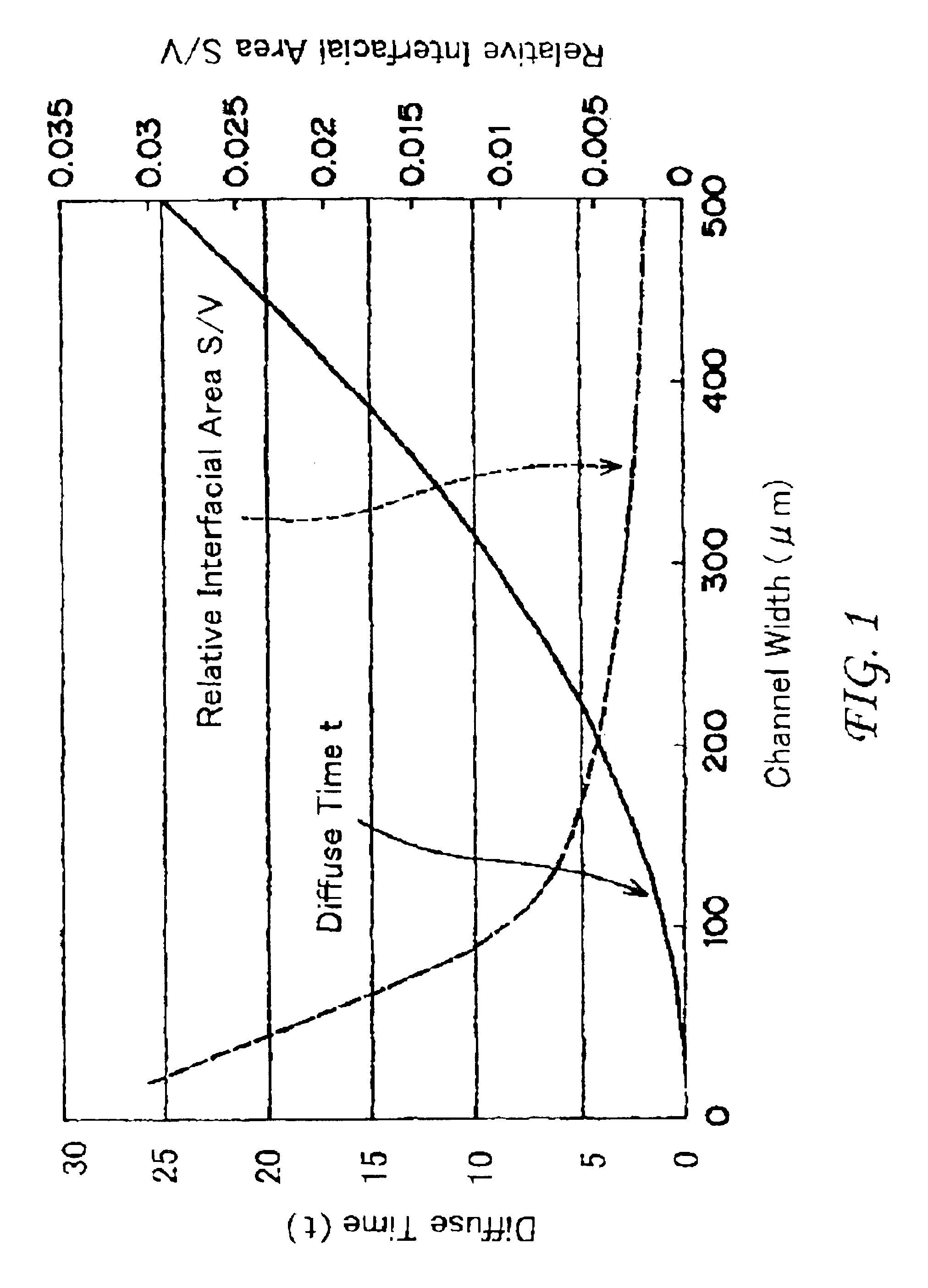
In the above-explained embodiments, the diffuse mixing can be carried out in a microarea efficiently.

The present invention is not limited to the above-mentioned embodiments, and the present invention can be carried out in various forms.

For example, the microchips 2 and 3 are be used not only for blood coagulation but can be used widely as main components of a micromixer for mixing a very small amount of liquids.


PUM

PropertyMeasurementUnit
widthaaaaaaaaaa
Reynolds numberaaaaaaaaaa
widthaaaaaaaaaa

Abstract

Disclosed herewith is a microchip having a micromixer therein. The mixromixer employs a mixing or extracting structure having (1) a first flow pass provided at a first level of the microchip; (2) a second flow pass provided at a second level of the microchip, which is different from the first level; (3) a third flow pass having a plurality of sub flow passes separately layered at the first level and each having a first end and second end thereof, each sub flow pass being connected to one of the first and second flow passes at the first end thereof; and (4) a fourth flow pass, provided at the first level, connected to the second ends of the sub flow passes so that, at least connecting portions between the fourth flow pass and the sub flow passes of the third flow pass, an extending direction of the fourth flow pass is substantially identical to those of the sub flow passes. By allowing the first liquid to flow from the first flow pass to the fourth flow pass through the third flow pass while the second liquid to flow from the second flow pass to the fourth flow pass through the third flow pass, the first and second liquids are mixed at the fourth flow pass.

Description

CROSS-REFERENCE TO RELATED APPLICATIONThis application is based on Japanese Patent Application No. 2001-182217 filed in Japan on Jun. 15, 2001, the entire content of which is hereby incorporated by reference.BACKGROUND OF THE INVENTION1. Field of the InventionThe present invention relates to a mixing method, a mixing structure, and a micromixer and a microchip having the mixing structure.2. Description of the Related ArtA μ-TAS (μ-Total Analysis System) has an exceptionally smaller size than that of a conventionally used appliance, i.e., a flask, a test tube and so on. For this reason, amount, cost and disposal of reagent or specimen can be suppressed, and thus an attention is paid to the μ-TAS as for one feature that synthesizing and detection with a very small amount are possible. The μ-TAS can be applied to a clinical analyzing chip, an environmental analyzing chip, a gene analyzing chip (DNA chip), a sanitary analyzing chip, a chemical / biochemical analyzing chip and the like.For...

Claims


Application Information

Patent Timeline
Patent Type & Authority Patents(United States)
IPC IPC(8): B01F13/00B01F5/04B01L3/00B01F3/08B01F5/00G01N37/00
CPCB01F5/0453B01F5/0458B01F13/0062B01F13/0093B01F13/0066B01L3/5027B01F2215/0431Y10T137/87652B01F25/31323B01F25/3132B01F33/3012B01F33/3011B01F33/3039
Inventor FUJII, YASUHISAYAMASHITA, SHIGEOSANDO, YASUHIROYAMAMOTO, KOJIHAYAMIZU, SHUNICHI
Owner MINOLTA CO LTD
Why Eureka
Try Eureka