
Planetary gearbox with integral electric motor and steering means.

a technology of electric motors and gearboxes, applied in the direction of gearing details, electric propulsion mounting, gearing, etc., can solve the problems of large electrical motor/gearbox combinations, inability to supplant hydraulic wheel motors, and substantial loss of system efficiency, and achieve the effect of greater efficiency

Inactive Publication Date: 2005-02-08
FAIRFIELD MFG CO INC
View PDF21 Cites 83 Cited by
  • Summary
  • Abstract
  • Description
  • Claims
  • Application Information

AI Technical Summary

Benefits of technology

The present invention comprises a useful and compact wheel motor drive arrangement for applications on such construction equipment as scissor lifts and other similar scaffolding equipment where hydraulically driven systems have historically been used to provide power to the wheels to move the equipment. The invention includes an electric motor mounted to a spindle bracket which is pivotably connected to the frame of the equipment to allow the unit to be pivoted around a vertical axis for steering purposes. A gear reducing planetary gear system is mounted around the drive shaft of the motor which is contained within the rotating wheel hub. The output ring gear of the planetary gear system is integrally formed to the interior of the wheel hub so that there is a direct application through the planetary gear system to the wheel hub to provide greater efficiency.
The present invention provides decided advantages over the low speed hydraulic wheel motors that are presently used to drive such compact scissor lift and other scaffolding equipment used in the construction industry. Hydraulic wheel motors have historically been used for such equipment due to their small size and relatively inexpensive cost. However, such hydraulic motors require an electrical motor and hydraulic pump to drive the hydraulic wheel motors which causes substantial loss of efficiency for the system. The present invention provides a highly efficient compact motor and planetary gear system which is far more efficient than the prior art hydraulic wheel motors, and which provides greater direct power to the wheels than prior art systems.
Historically, electrical motor / gearbox combinations have been too large and too complex to supplant hydraulic wheel motors for small compact scaffold and scissor lift equipment. However, the present invention provides a unique, compact, and efficient arrangement which reduces the overall size while maintaining and increasing the power and efficiency to the drive wheels. Further, present invention allows much quieter operation with the elimination of hydraulic fluid leaks which can cause safety and cleanliness problems at construction sites. The present invention is typically mounted in pairs that are interconnected by a tie bar so that both the wheel motors can be pivoted about the vertical axis of the spindle to permit the steering of the equipment during movement.
Thus, it is a primary object of the present invention to provide a compact, efficient electric wheel motor arrangement for scissor lifts and similar scaffolding equipment which can be economically used to eliminate low speed hydraulic wheel motors.
It is yet another object of the present invention to provide a steerable wheel motor for scissor lifts and other scaffolding equipment which can be used both to drive the movement of the equipment as well as steer the equipment during movement.

Problems solved by technology

Hydraulic wheel motors have historically been used for such equipment due to their small size and relatively inexpensive cost.
However, such hydraulic motors require an electrical motor and hydraulic pump to drive the hydraulic wheel motors which causes substantial loss of efficiency for the system.
Historically, electrical motor / gearbox combinations have been too large and too complex to supplant hydraulic wheel motors for small compact scaffold and scissor lift equipment.

Method used


Image

  • Planetary gearbox with integral electric motor and steering means.
  • Planetary gearbox with integral electric motor and steering means.
  • Planetary gearbox with integral electric motor and steering means.

Examples


Embodiment Construction

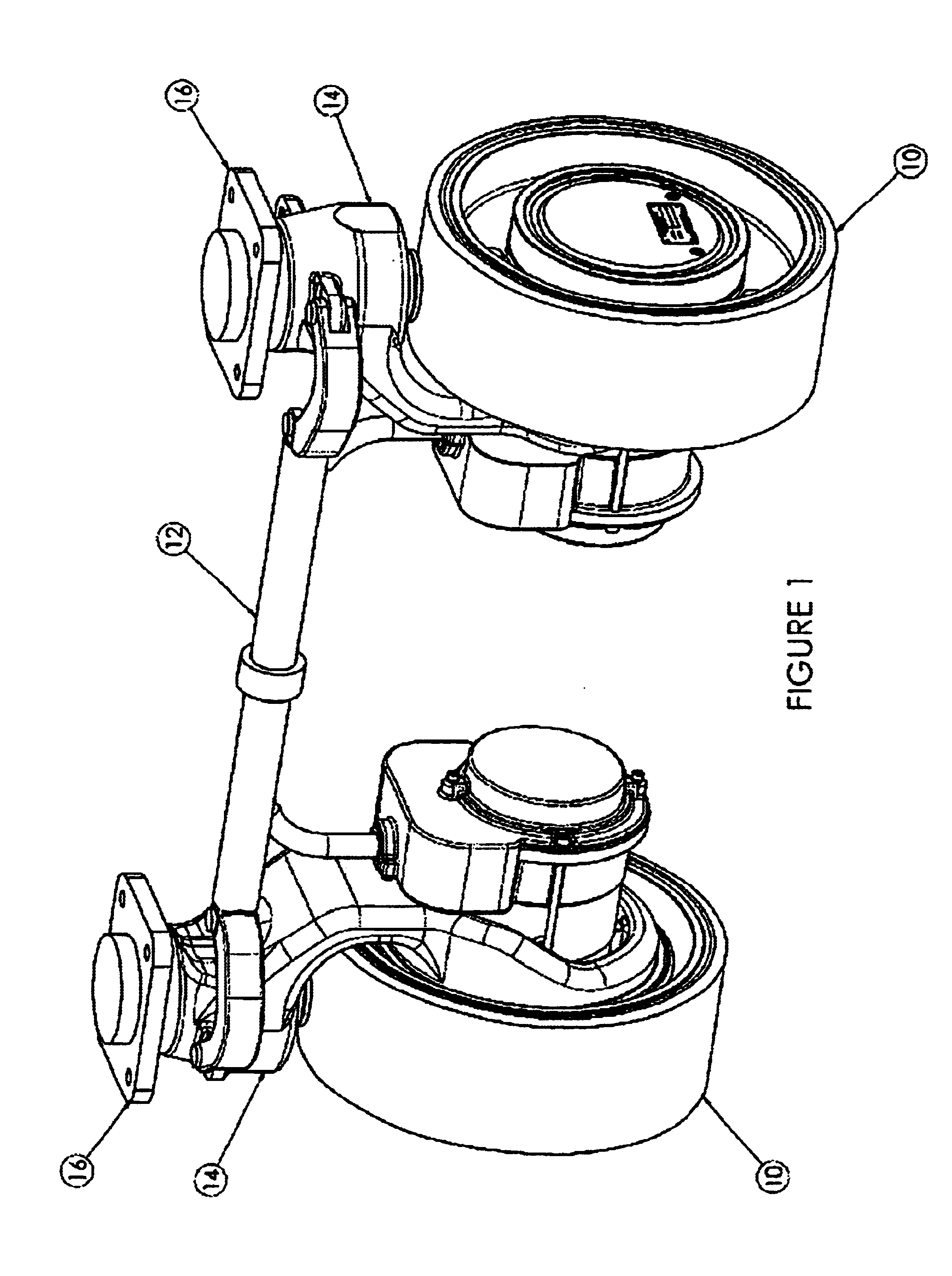
With respect to FIG. 1, two wheel motor assemblies 10 are shown in a paired relationship with an interconnecting tie bar assembly 12 which is pivotably connected at each end to spindle brackets 14. Spindle brackets 14 are pivotably mounted on a shaft (not shown) extending downwardly from brackets 16. Brackets 16 can be mounted to the appropriate undercarriage of the scissor lift or other scaffold equipment (not shown). Tie bar assembly 12 is connected to the steering mechanism of the equipment (not shown) so that the tie bar can be moved laterally to cause the wheel motor assemblies to pivot around the shaft to steer the equipment.

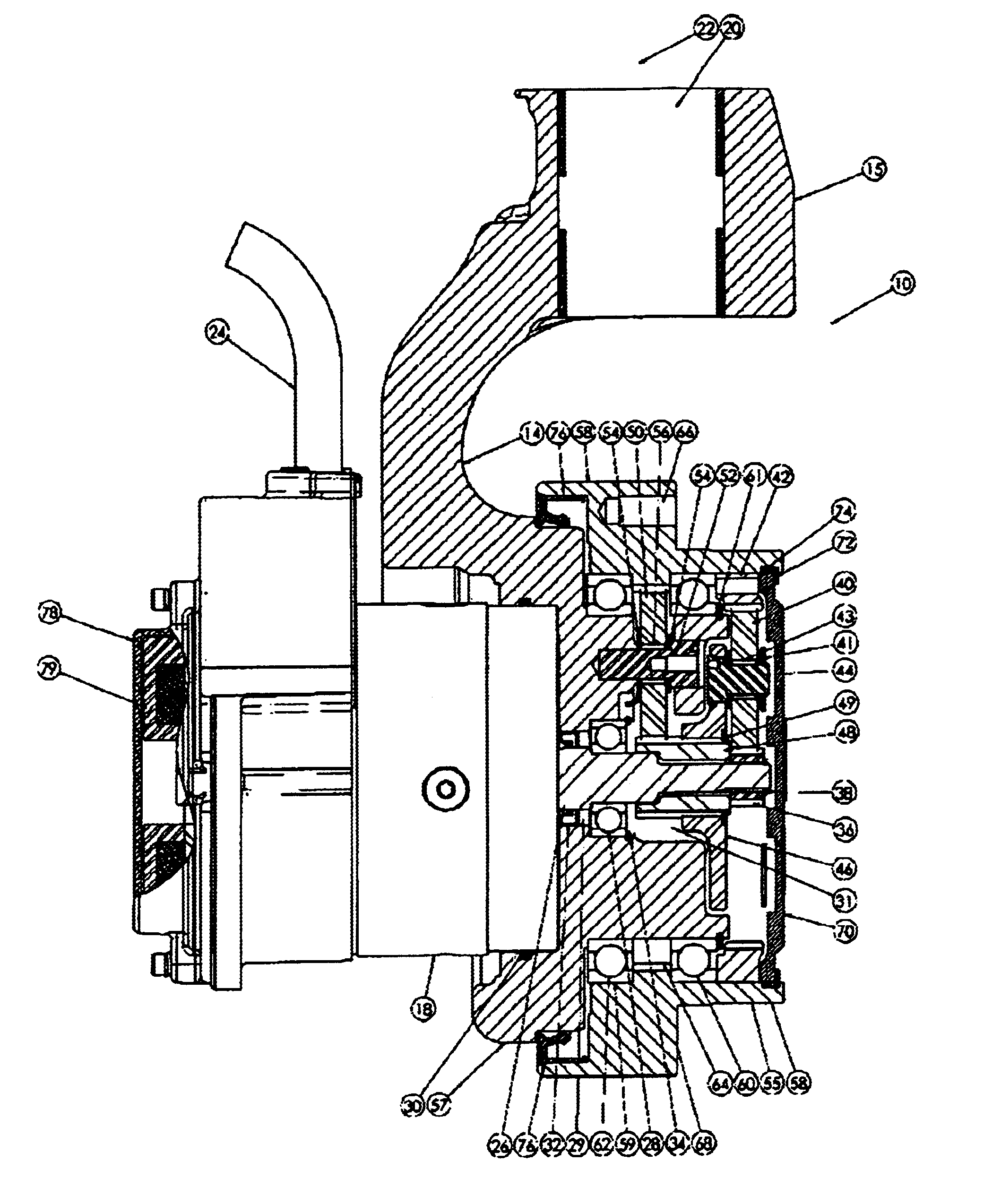
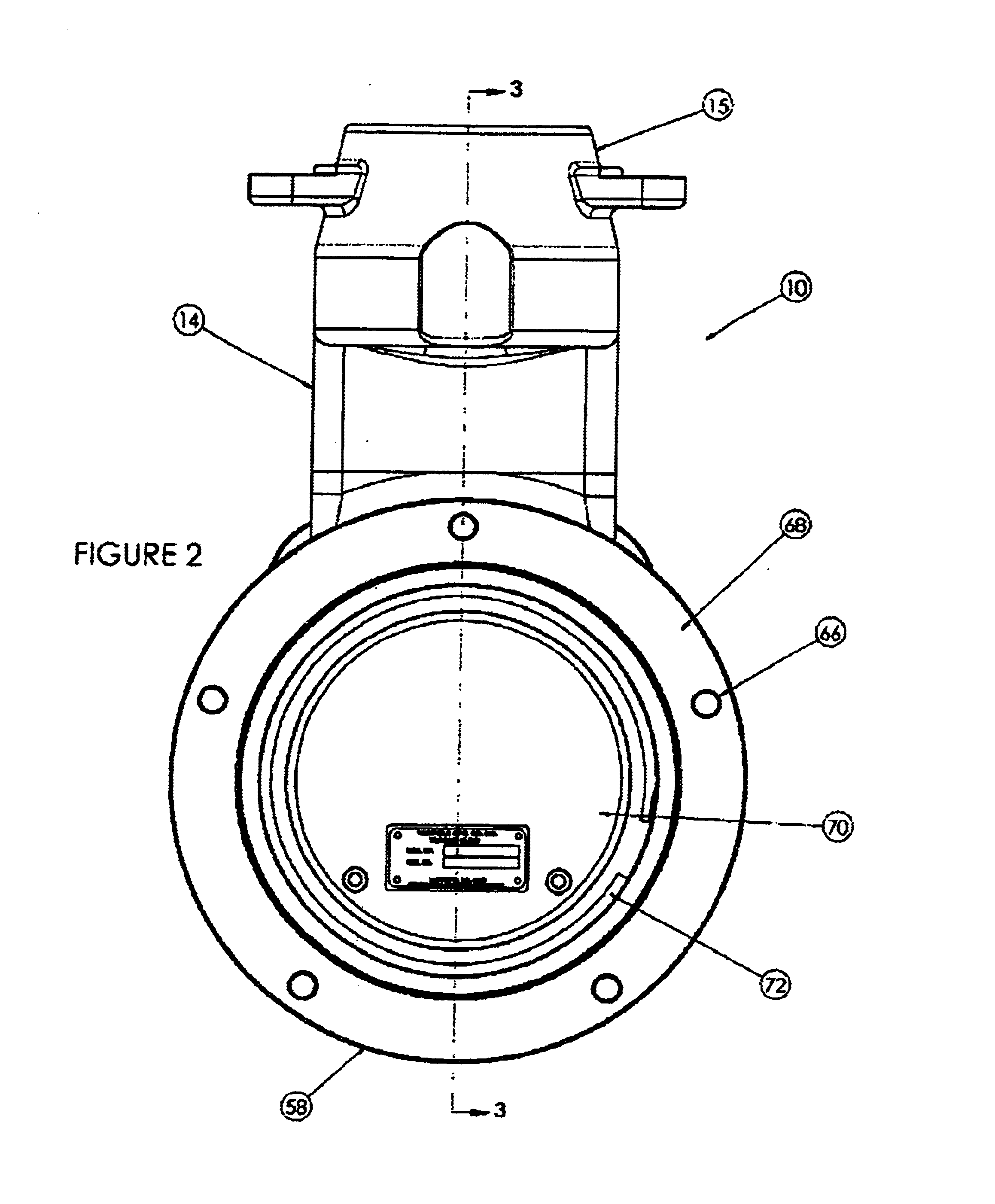
With reference to FIGS. 2 and 3, wheel motor assembly 10 comprises spindle bracket 14 to which is mounted motor 18. The upper end 15 of spindle bracket 14 has a hollow cylindrical opening 20 formed throughout which is dimensional to receive the cylindrical shaft (not shown) mounted on bracket 16 so that the spindle bracket 14 can pivot about vertical axis ...


PUM


Abstract

A new, useful and compact wheel motor drive arrangement for applications on such construction equipment as scissor lifts and other similar scaffolding equipment where hydraulically driven systems have historically been used to provide power to the wheels to move the equipment is disclosed. An electric motor is mounted to a spindle bracket which is pivotably connected to the frame of the equipment to allow the unit to be pivoted around a vertical axis for steering purposes. A gear reducing planetary gear system is mounted around the drive shaft of the motor is positioned totally within the rotating wheel hub. The output ring gear of the planetary gear system is integrally formed to the interior of the wheel hub so that there is a direct application through the planetary gear system to the wheel hub to provide greater efficiency.

Description

BACKGROUND OF THE INVENTIONField of the InventionThis invention relates generally to electrical wheel motor drive systems for construction equipment and more particularly for small, compact construction equipment such as scissor lifts and scaffolding. More particularly, this invention combines a planetary gear box, an electrical motor and steering arm into one compact package which allows the wheel motor to act as both the drive wheel and steering wheel for the equipment.SUMMARY OF THE INVENTIONThe present invention comprises a useful and compact wheel motor drive arrangement for applications on such construction equipment as scissor lifts and other similar scaffolding equipment where hydraulically driven systems have historically been used to provide power to the wheels to move the equipment. The invention includes an electric motor mounted to a spindle bracket which is pivotably connected to the frame of the equipment to allow the unit to be pivoted around a vertical axis for stee...

Claims


Application Information

Patent Timeline
IPC IPC(8): B60K7/00B60K17/04B60K17/30B60K17/00
CPCB60K7/0007B60K17/046B60K17/30B60Y2200/49B60K2007/0046B60K2007/0092
Inventor SCHOON, BENJAMIN WARREN
Owner FAIRFIELD MFG CO INC
Learn More