Apparatus and methods for fourier spectral analysis in a scanning spot microscope

a scanning spot microscope and spectral analysis technology, applied in the field of scanning spot microscopes, can solve the problems of loss of light in filters or monochromators, serious problems, and sacrifice of at least half of the intensity of incident light, and achieve the effect of reducing the operating range of wavelength, and reducing the cost of operation

Inactive Publication Date: 2005-02-08
BIO RAD LAB INC
View PDF5 Cites 20 Cited by
  • Summary
  • Abstract
  • Description
  • Claims
  • Application Information

AI Technical Summary

Benefits of technology

A preferred form of interferometer, which is suited to low-light-level conditions, has a polarizing beamsplitter (of which the preferred version is a cube polarizing beamsplitter of the dielectric type) placed in the path of the input light. This beamsplitter functions to divide the input beam of light into two beams of mutually perpendicular polarization, both of which enter the interferometer. As a result, incoming light having any direction of polarization is transmitted into the interferometer with minimum loss. After passage through the birefringent device both beams pass through a second polarizing beamsplitter, used in this case as a beam-combiner. In this preferred form of the interferometer the two beams passing through the interferometer define a rectangular shape, in which one vertex corresponds to the point of separation of the beams and the opposite vertex to their point of recombination. There are two exit paths for the light, which are directed into two detectors, preferably photomultipliers. This design allows the total optical efficiency to approach 100%.
Optionally included in this preferred form of the interferometer is a modified Soleil compensator, in which a wedge of birefringent material is translated relative to fixed path-defining optics. In the modified Soleil compensator the optical slow direction of the birefringent wedge is at an angle of 45° to its direction of translation, instead of being in the usual orthogonal direction. This advantageously allows the optical path difference between differently-polarized components in opposite and parallel legs of the rectangular beam path to be the same for all positions of the wedge, which is translatable in a directi...

Problems solved by technology

In such a situation, loss of light in filters or monochromators, which are frequently used to isolate light of specific wavelengths before passage to the detector, is a serious problem.
At first sight, an objection to Mertz's apparatus is that since it requires a polarized input, at least half of the intensity of the incident light is sacrificed.
The prior art works well, but none of it is directed towards the application of int...

Method used


Image

  • Apparatus and methods for fourier spectral analysis in a scanning spot microscope
  • Apparatus and methods for fourier spectral analysis in a scanning spot microscope
  • Apparatus and methods for fourier spectral analysis in a scanning spot microscope

Examples


Embodiment Construction

Further features and advantages of the invention will be apparent from the following description of embodiments, making reference to the accompanying drawings, in which:

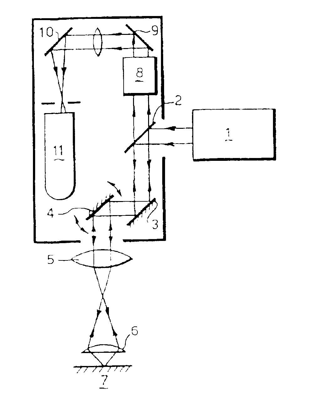
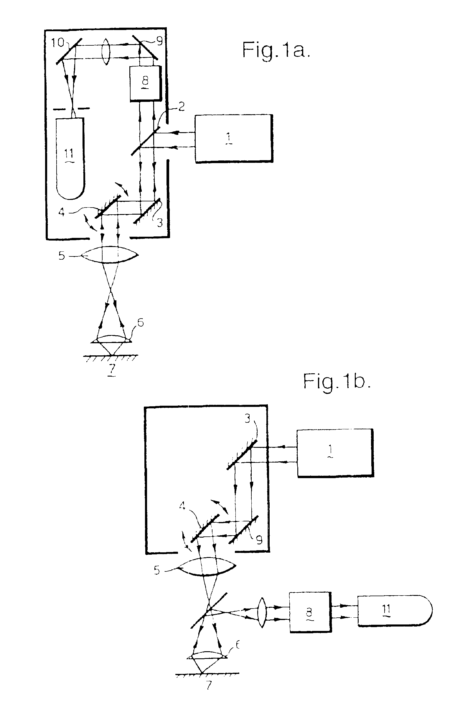
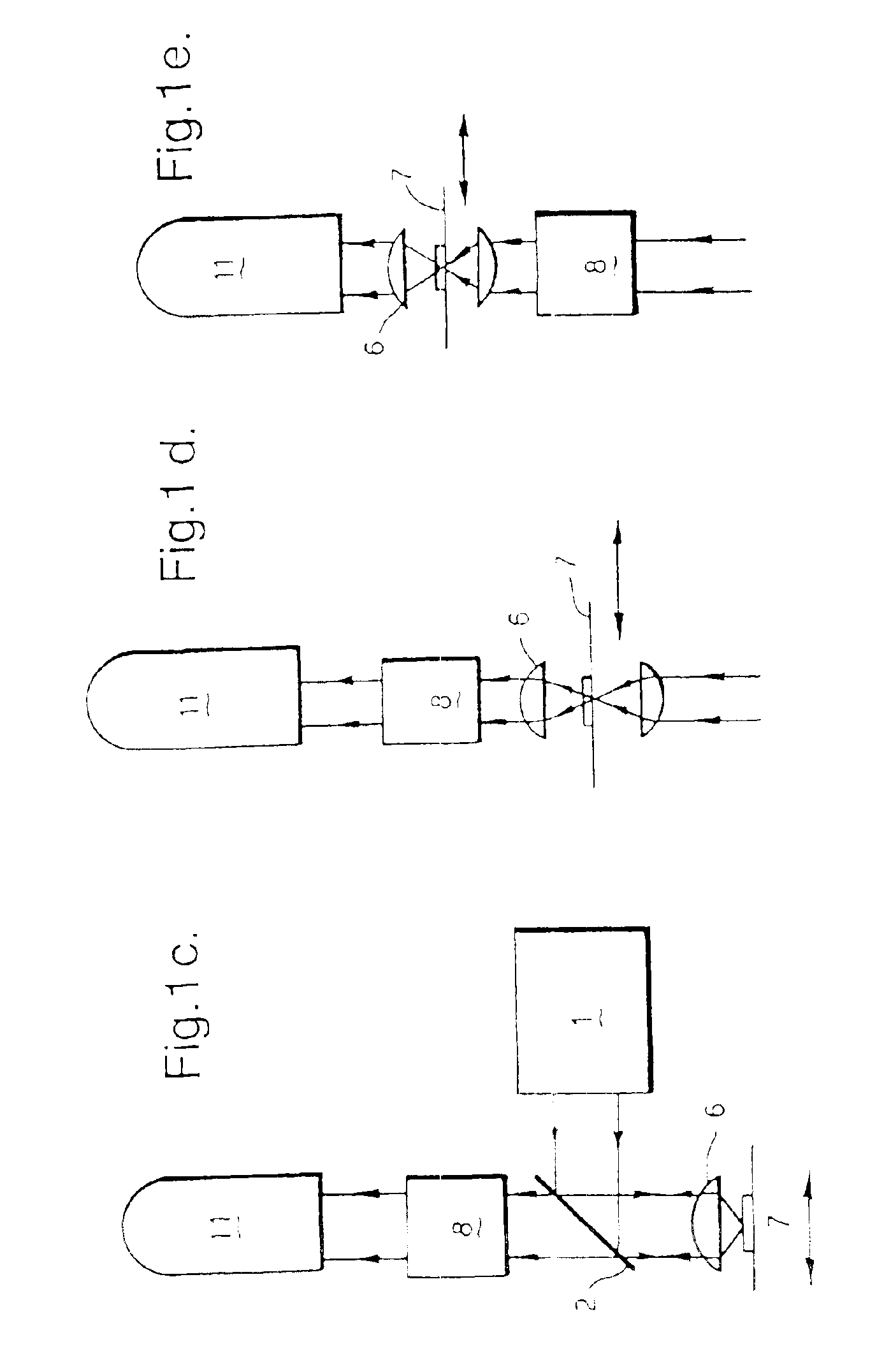
FIGS. 1a, 1b, 1c, 1d and 1e show schematically examples of scanning spot microscopes and various ways in which an interferometer may be incorporated into them. For simplicity, single detectors are shown in diagrams, although in the microscopes at FIGS. 1a-1d a pair of detectors may be used.

FIG. 2 shows an interferometer suitable for relatively high intensities of light (e.g. for measurements of absorption spectra of stained microscope specimens).

FIG. 3 shows an interferometer similar to that of FIG. 2 in which a polarizing beamsplitter is substituted for the analyzer.

FIG. 4 shows a more preferred polarizing interferometer suitable for lower intensities of light.

In FIG. 1a an epi-fluorescence or epi-reflection microscope is shown, in the form frequently used for confocal microscopy. Light from a laser 1 is reflected o...


PUM


Abstract

A scanning spot microscope for performing a Fourier spectral analysis has means for performing a repeatable scanning operation which includes scanning an incident light spot to successive locations of a specimen. An interferometer is placed across an optical light path of the microscope, the interferometer including a birefringent device between polarizing devices in the path and introducing a given path difference. Means are provided for receiving and recording an optical signal due to the incident light spot from each successive specimen location. In use the given path difference is maintained during each scanning operation but is varied between scanning operations so that the optical signals relating to these specimen locations and the values of the given path difference can be recorded.

Description

FIELD OF THE INVENTIONThis invention relates to a scanning spot microscope including apparatus for Fourier spectral analysis and methods for operating it.BACKGROUND OF THE INVENTIONOptical microscopes in which a point or, more exactly, a very small volume (say 1 μm3 or less, e.g. of the order of 0.01 μm3) of the specimen is illuminated at any one time have been developed for a number of different optical imaging methods, including confocal epifluorescence imaging (White, U.S. Pat. No. 5,032,720) and multiphoton imaging (Denk, Strickler and Webb, U.S. Pat. No. 5,034,613). Some of these methods are reviewed in the Handbook of Biological Confocal Microscopy, edited by James B. Pawley, Second Edition, Plenum Press (1995). In the case of a so-called scanning spot microscope, an image is built up by scanning the illumination spot over the specimen or by scanning the specimen relative to a stationary spot, some portion of the emitted or reflected radiation being measured over a period of t...

Claims


Application Information

Patent Timeline
IPC IPC(8): G02B21/00G02B5/30G01N21/64G01N21/27G02B21/16
CPCG02B21/002G02B5/3083
Inventor DIXON, ANDREWAMOS, WILLIAM BRADSHAW
Owner BIO RAD LAB INC
Why Eureka
Try Eureka