
Isolated voltage regulator with one core structure

Inactive Publication Date: 2005-02-08
DELTA ELECTRONICS INC
View PDF7 Cites 50 Cited by
  • Summary
  • Abstract
  • Description
  • Claims
  • Application Information

AI Technical Summary

Benefits of technology

It is therefore an object of the present invention to propose a new structure for a high input VRM. This structure should be similar to a simple buck converter and can simplify the 48V input VRM design.
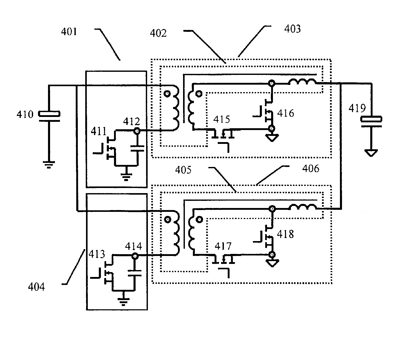
In order to supply much higher load current, two rectifier circuits can be arranged in parallel. The structure can lower the winding current by a half and then reduce the total copper loss.
The rectifier circuits also can be arranged in series in the primary side of the transformer. It will reduce the turn ratio of transformer and then improve the transformer coupling. Good coupling is beneficial to lower leakage inductance and then to reduce the dead time for an output current commutation. When the conduction time for body diode is reduced, the whole efficiency will be improved.

Problems solved by technology

However, the high input current in 12V or 5V input VRM will cause high power loss on the input power bus, and a large input filter is also needed for the increasing transient demand.
But this scheme has too big size because too many semiconductors and at least two magnetic devices should be used.
The control is also complex because two controllers should be used.
Generally, this scheme increases the VRM's cost, profile and complicity for productivity.

Method used


Image

  • Isolated voltage regulator with one core structure
  • Isolated voltage regulator with one core structure
  • Isolated voltage regulator with one core structure

Examples


Embodiment Construction

Although this invention is susceptible to embodiments of many different forms, a preferred embodiment will be described and illustrated in detail herein. The present disclosure exemplifies the principle of the invention and is not being considered a limitation to the broader aspects of the invention to the particular embodiment as described.

Referring to FIG. 4, there is the present solution with a simple circuit, low profile and low cost. In this topology, the number of interleaving channels is at least two and the phase difference between each adjacent interleaving channel is 360 degree divided by the number of channels interleaved.

FIG. 5 shows a basic cell for the present topology. A DC voltage Vin at an input capacitor 510 is connected to the output lead through a rectifier circuit 502, and a switch 511. In the rectifier circuit 502, the transformer 513 is integrated into the output inductor 514. So it involves one magnetic device 501 just like that in the buck rectifier circuit....


PUM


Abstract

The present invention proposes a new structure for a high input VRM. This structure is similar to a simple buck converter and can simplify the 48V input VRM design. In this present invention, the interleaved voltage regulator is provided. The interleaved voltage regulator includes an integrated magnetic device for performing both transformer and output choke filter function, a first switch, a second switch, a third switch, and a fourth switch, wherein the integrated magnetic device includes a transformer having a first primary winding, a second primary winding, a first secondary winding, and a second secondary winding, a first choke filter having one end coupled to a first terminal of the first secondary winding, and a second choke filter having one end coupled to a first terminal of the second secondary winding, and the other end of the second choke filter coupled to the other end of the first choke filter to form the output terminal of the isolated voltage regulator. The first switch, the second switch, the first choke filter, and the first secondary winding form a synchronous rectifier circuit. The third switch, the fourth switch, the second choke filter, and the second secondary winding form another synchronous rectifier circuit.

Description

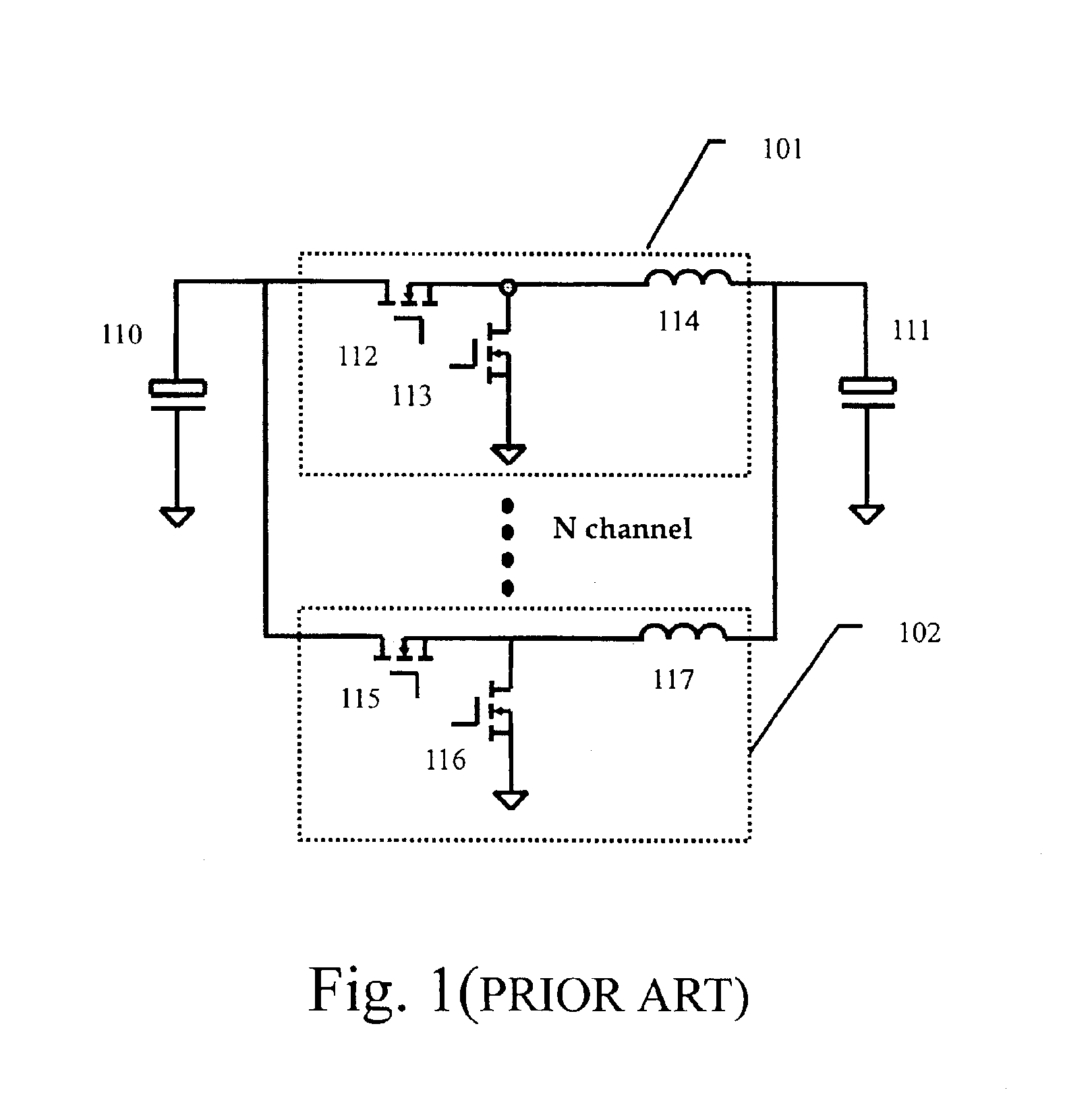
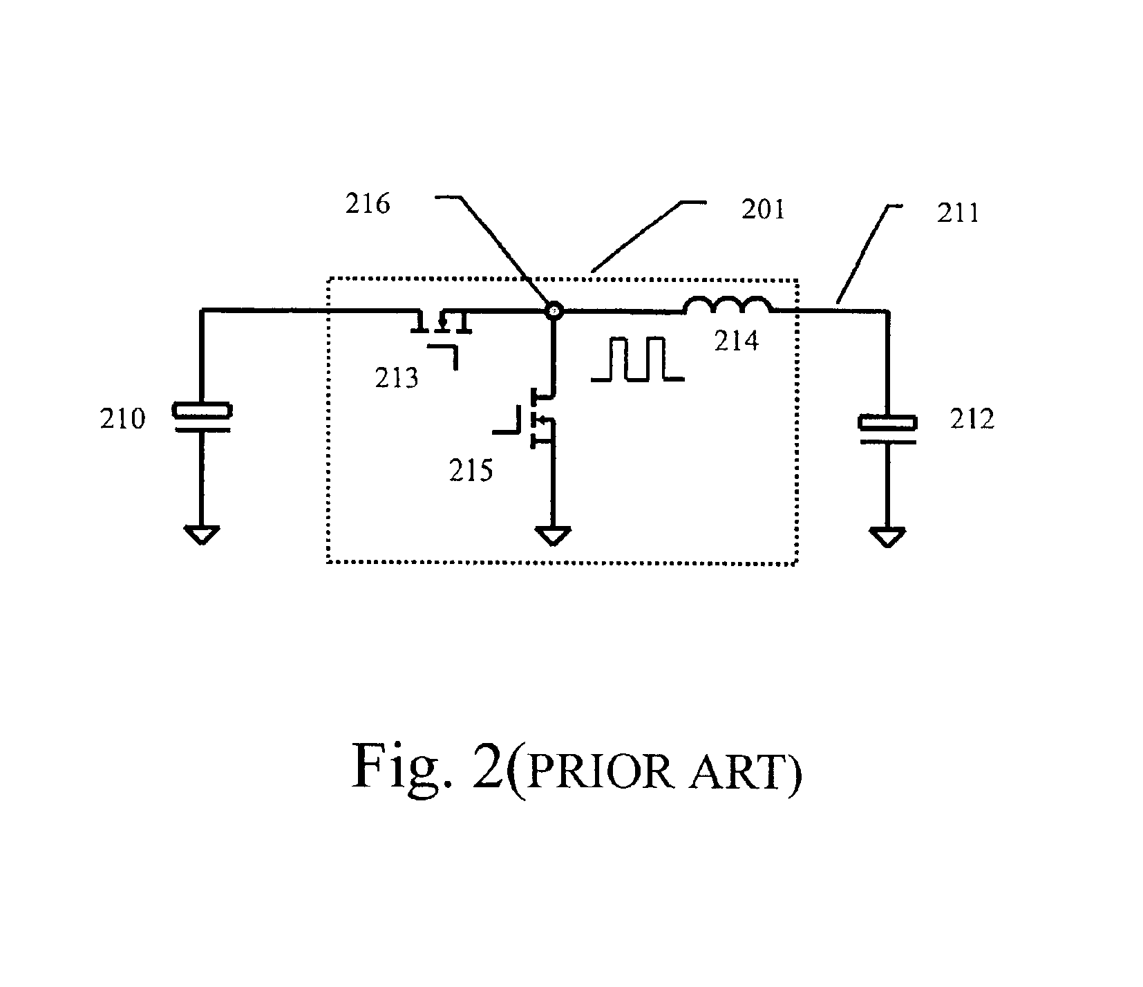
FIELD OF THE INVENTIONThis invention generally relates to a voltage regulator which is used to supply a processor or memory with a low voltage and high current, and more particularly to an isolated high input voltage regulator with one core structure.BACKGROUND OF THE INVENTIONModern processors operate under a very low voltage and a high current to meet the demands for faster and more efficient data processing. The voltage regulator module (VRM) must be used to provide power for the microprocessors.Please refer to FIG. 1, there is depicted an interleaved synchronous buck topology with at least two interleaving channels that is widely used in 5V / 12V input VRM. The phase difference between each adjacent interleaving channel is 360 degree divided by the number of channels interleaved.FIG. 2 shows a basic cell for interleaved synchronous buck converter shown in FIG. 1. A DC voltage input Vin at an input capacitor 210 is connected to the output lead 211 through a rectifier circuit 201, s...

Claims


Application Information

Patent Timeline
IPC IPC(8): H02M3/335H02M3/24
CPCH02M3/33592Y02B70/1475Y02B70/10
Inventor LI, WENHUAKE, ZHONGWEIHUANG, GUISONGZHANG, ALPHA J.
Owner DELTA ELECTRONICS INC
Learn More