Electrophotographic photoreceptor and image forming apparatus using the photoreceptor

a photoreceptor and photoreceptor technology, applied in the field of electrotrophotographic photoreceptors, can solve the problems of deterioration of the charge potential and photosensitivity of the resultant photoreceptors, background fouling, deterioration of the resultant image density and quality, etc., to achieve high-quality image production, high durability, and high-speed printing

Inactive Publication Date: 2005-02-08
RICOH KK
View PDF13 Cites 21 Cited by
  • Summary
  • Abstract
  • Description
  • Claims
  • Application Information

AI Technical Summary

Benefits of technology

Accordingly, an object of the present invention is to provide an image forming apparatus, a tandem-type full color image forming apparatus and a process cartridge, which realize high-speed printing, high-quality image production and high durability simultaneously.

Problems solved by technology

Typically, a low-molecular-weight charge transport material used in a CTL is dispersed and mixed with an inactive polymer because the charge transport material is not capable of forming a film alone.
Therefore, a coated film of the CTL is largely abraded due to repeated use in the Carlson process, resulting in deterioration of charge potential and photosensitivity of the resultant photoreceptor, background fouling due to a damage of a surface thereof and deterioration of the resultant image density and quality.
However, the above-mentioned electrophotographic photoreceptor having a thick photosensitive layer is disadvantageous for higher image quality because a charge injected in the CTL does not smoothly reach a surface of the photoreceptor to neutralize the surface charge, which causes blurred images.
Further, the thicker the CTL, the influence significantly causes deterioration of the resultant image quality.
However, the thin CTL causes deterioration of sensitivity as mentioned above.
However, when the surface potential is decreased, a surface potential difference between an irradiated part and a non-irradiated part becomes small and it becomes difficult to form a sharp electrostatic latent image.
Further, when a photoreceptor is electrostatically fatigued due to repeated use, chargeability of the photoreceptor deteriorates and residual potential thereof increases.
Therefore, the surface potential difference between an irradiated part and a non-irradiated part becomes smaller, resulting in abnormal images such as background fouling and deterioration of image density.
As mentioned above, it has been quite difficult for a conventional image forming apparatus to realize high-speed printing, high-quality image production and high durability simultaneously.

Method used


Image

  • Electrophotographic photoreceptor and image forming apparatus using the photoreceptor
  • Electrophotographic photoreceptor and image forming apparatus using the photoreceptor
  • Electrophotographic photoreceptor and image forming apparatus using the photoreceptor

Examples


example 1

The following materials were mixed and dispersed in a ball mill for 12 hrs to prepare an undercoat layer coating liquid:

Alkyd resin15(Bekkolite M6401-50 from Dainippon Ink &Chemicals, Inc.)Melamine resin10(Super Bekkamin G-821-60 from Dainippon Ink &Chemicals, Inc.)Methyl ethyl ketone150Titanium oxide powder90(Tipaque CR-E1 from Ishihara Sangyo Kaisha, Ltd.)

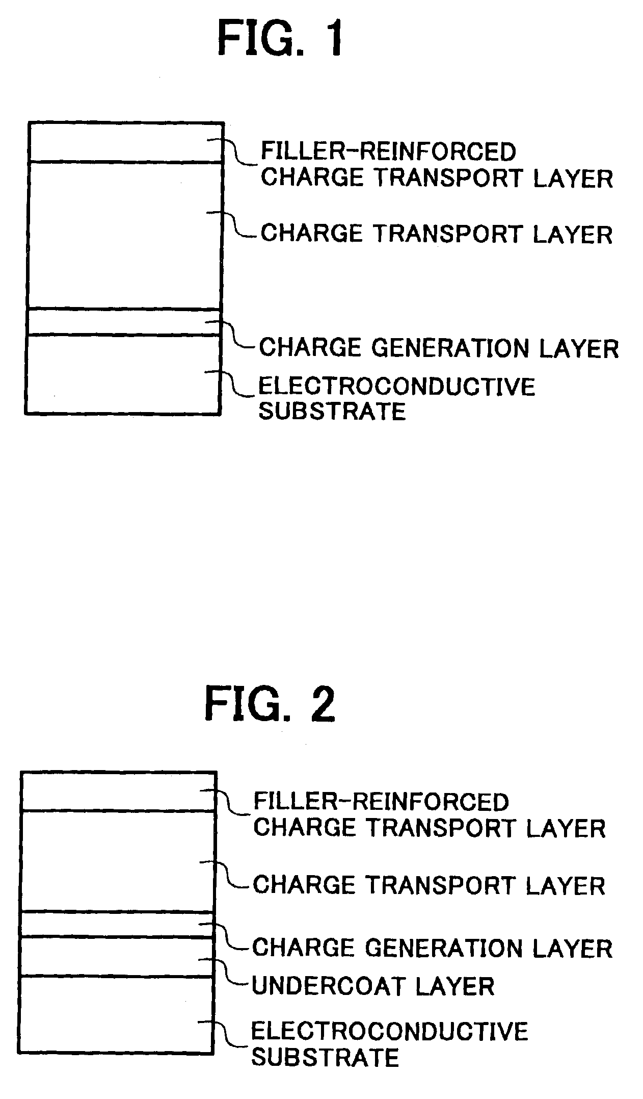
The thus prepared undercoat layer coating liquid was coated on a cylindrical aluminium substrate having an outer diameter of 100 mm by a dip coating method, and the coated liquid was dried at 30° C. for 20 min to form an undercoat layer having a thickness of 3.5 μm on the substrate.

Polyvinylbutyral resin5(S-lec HL-S from Sekisui Chemical Co., Ltd.)2-butanone150Titanylphthalocyanine8having XD spectrum shown in FIG. 7

Further, 250 parts by weight of 2-butanone were included in the mixture and the mixture was dispersed for 3 hrs. The thus prepared CGL coating liquid was coated on the undercoat layer by a dip coating method, and the l...

example 2

The procedures of preparation and evaluation for the photoreceptor in Example 1 were repeated except that the thicknesses of the CTL and filler-reinforced layer were changed to 10 μm and 3 μm respectively, and that the potential of non-irradiated part of the photoreceptor was changed to −700 V.

example 3

The procedures of preparation and evaluation for the photoreceptor in Example 1 were repeated except that the thicknesses of the CTL and filler-reinforced layer were changed to 15 μm and 3 μm respectively, and that the potential of non-irradiated part of the photoreceptor was changed to −600 V.


PUM


Abstract

An electrophotographic photoreceptor includes an electroconductive substrate. A charge generation layer overlies the electroconductive substrate. A first charge transport layer overlying the charge generation layer includes a first charge transport material (D1) and a first binder resin (R1). A second charge transport layer overlying the first charge transport layer includes a filler, a second charge transport material (D2) and a second binder resin (R2). The first and second charge transport layers have a total thickness of from 5 to 25 μm. A weight ratio (D1 / R1) of the first charge transport material (D1) to the first binder resin (R1) in the first charge transport layer is greater than a weight ratio (D2 / R2) of the second charge transport material (D2) to the second binder resin (R2) in the second charge transport layer.

Description

CROSS-REFERENCE TO RELATED APPLICATIONThis application claims benefit of priority to Japanese application no. 2002-065052, filed March 11, 2002, the disclosure of which is incorporated by reference herein in its entirety.BACKGROUND OF THE INVENTION1. Field of the InventionThe present invention relates to an electrophotographic photoreceptor, as well as an image forming apparatus and a process cartridge using the photoreceptor, which realize high-speed printing, high-quality image production and high durability simultaneously.2. Discussion of the BackgroundRecently, data processing systems using electrophotographic methods have made remarkable progress. In particular, laser printers and digital copiers which record data with light by changing the data into digital signals have made remarkable improvements in their printing qualities and reliabilities. Further, technologies used in these printers and copiers have been applied with high-speed printing technologies to laser printers and...

Claims


Application Information

Patent Timeline
Patent Type & Authority Patents(United States)
IPC IPC(8): G03G5/043G03G5/047G03G5/05G03G15/02G03G15/01G03G15/04G03G15/043G03G15/16
CPCG03G5/047G03G5/0507Y10S430/103
Inventor SUGINO, AKIHIROKITAJIMA, RYOHICHIKAWASAKI, YOSHIAKIIKEGAMI, TAKAAKIKURIMOTO, EIJI
Owner RICOH KK
Why Eureka
Try Eureka