Method and apparatus for storage tank leak detection

a technology for storage tanks and leak detection, applied in the direction of volume measurement, liquid/fluent solid measurement, volume measurement, etc., can solve the problems of high detection threshold, easy to see leak protection and detection difficulties, and difficulty in preventing leakage of storage tanks, etc., to preserve industrial and environmental resources. , the effect of low detection threshold

Inactive Publication Date: 2005-02-15
MASS TECH
View PDF2 Cites 15 Cited by
  • Summary
  • Abstract
  • Description
  • Claims
  • Application Information

AI Technical Summary

Benefits of technology

In view of the foregoing, it is an object of the present invention to provide a storage tank leak detection apparatus with a very low detection threshold that may be used in an efficient manner thereby preserving industrial and environmental resources.
The method and apparatus of the present invention provides a safe and effective way to detect very small leaks in very large tanks. Particularly, the present invention provides a tremendous improvement in accuracy and leak detection threshold, allowing its users to achieve greater results than presently thought possible.

Problems solved by technology

That is, storage tank owners are willing to invest huge sums of money in both the maintenance and inspection of such tanks.
As one could imagine, there is a wide range of problems associated with maintaining storage tank integrity, particularly with above ground storage tanks.
Given the enormous dimensions of above ground tanks, the corrosive products contained within the tanks, the incredible mass of the stored product, and the extreme weather conditions the tanks are subjected to; it is plain to see that above ground storage tank leaks are an all-to-common problem.
Given the limited number of systems capable of meeting the EPA's underground storage tank leak detection threshold and the added difficulties associated with above ground tanks, the difficulty in protecting against and detecting leaks is easily seen.
However, the recognized difficulty in preventing storage tank leaks does not mitigate the duties or liabilities imposed on responsible parties.
Tremendous environmental and economic consequences and the threat of litigation and clean up costs associated with storage tank leaks force responsible parties to invest large sums of money in the maintenance and inspection of the tanks.
Tank inspections are costly with respect to the amount of money spent, the danger presented to the inspectors and the environment, and production downtime.
In fact, these inspections often remove a tank from service for more than one month.
The threat of liability also forces responsible parties to spend money unnecessarily for the maintenance of these tanks.
Currently, responsible parties are, in some countries, being incarcerated as a direct result of storage tanks leaks.
These leaks have contaminated surrounding ground water, some of which serves as drinking water for local residents.
Each day the shuttered facilities remain inoperative adds to an already tremendous amount of money lost.
Presently available leak detection systems lack detection thresholds low enough to detect leaks down to permissible upper leakage limits for above ground storage tanks.
Storage tank leak detection systems are known in the art; however, these products are fraught with problems.
The present systems are imprecise, or provide erroneous data for any or all of reasons including: the consistency of the soil acting as the tank's foundation, the temperature stratification of the in-tank product, extraneous noise sources, thermal expansion of the tank's contents, water table level, previous soil contamination, and / or tank shell dynamics.
Further, some detection devices can only be used when the storage tank is empty, and no known system or method ensures a comprehensive inspection of the tank.
The most common form of such a system is “vacuum box testing;” however, this system is intended only for weld joints and is not usually applied to the entire tank bottom.
Magnetic flux floor scanning is also used, but is not effective at examining the area of the floor surface close to the surface walls or where there are physical obstructions.
Ultrasonic detection is used, but this is only effective for small areas of the surface.
Gas detection is also used, but the types of materials stored in the tank can obstruct this method.
However, even large volume changes produce only small level changes, as the cross-sectional area of the liquid surface in these tanks is very large.
This, combined with differential expansion and temperature change of the stored liquid and its vapor, make this type of detection system inconsistent and very nearly worthless.
Present mass measurement leak detection systems in the art are limited by tank shell variations resulting from temperature effects on tank shell plating.
As such, known mass measurement detection systems are only sensitive enough to be used in smaller tanks, typically underground storage tanks.

Method used


Image

  • Method and apparatus for storage tank leak detection
  • Method and apparatus for storage tank leak detection
  • Method and apparatus for storage tank leak detection

Examples


Embodiment Construction

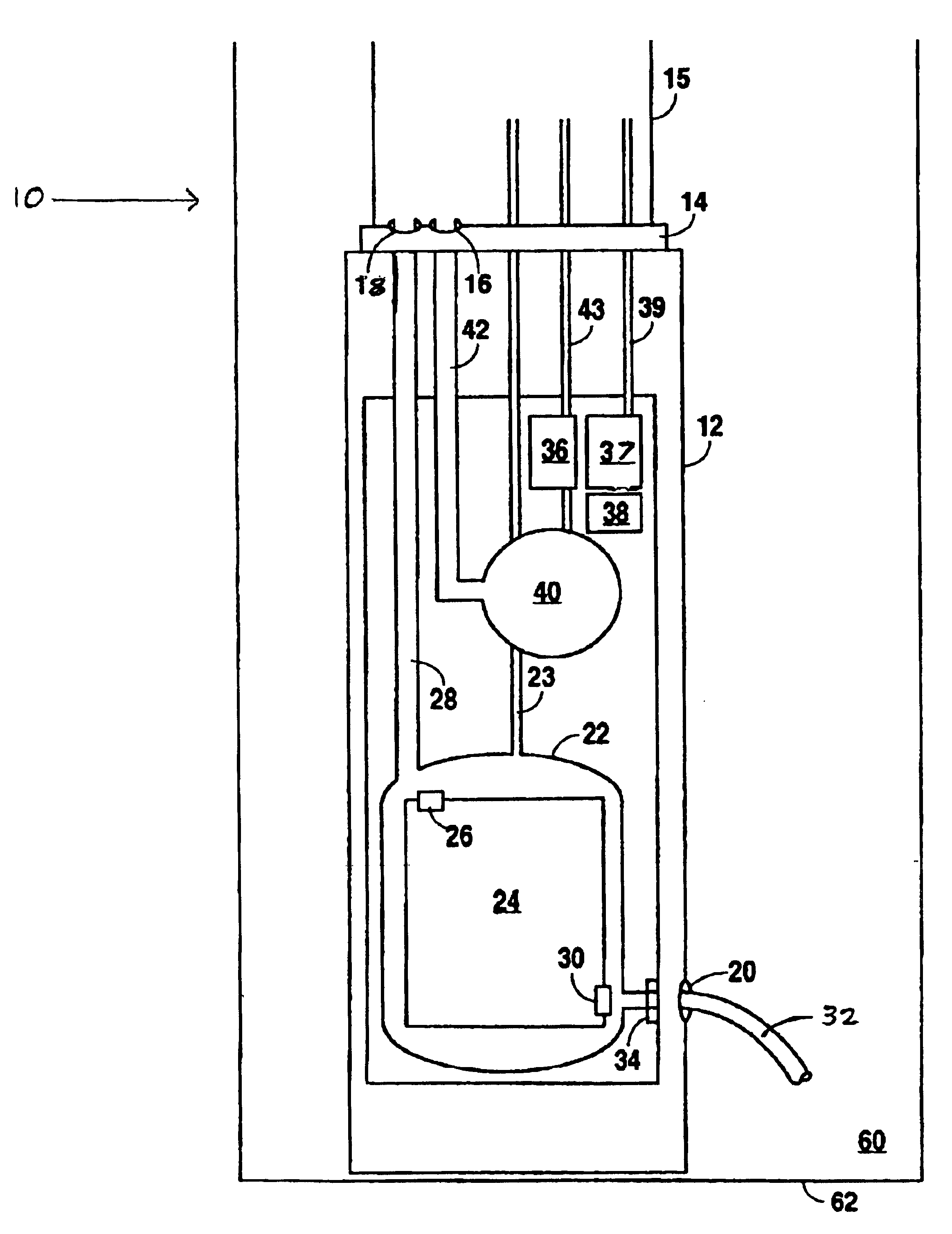
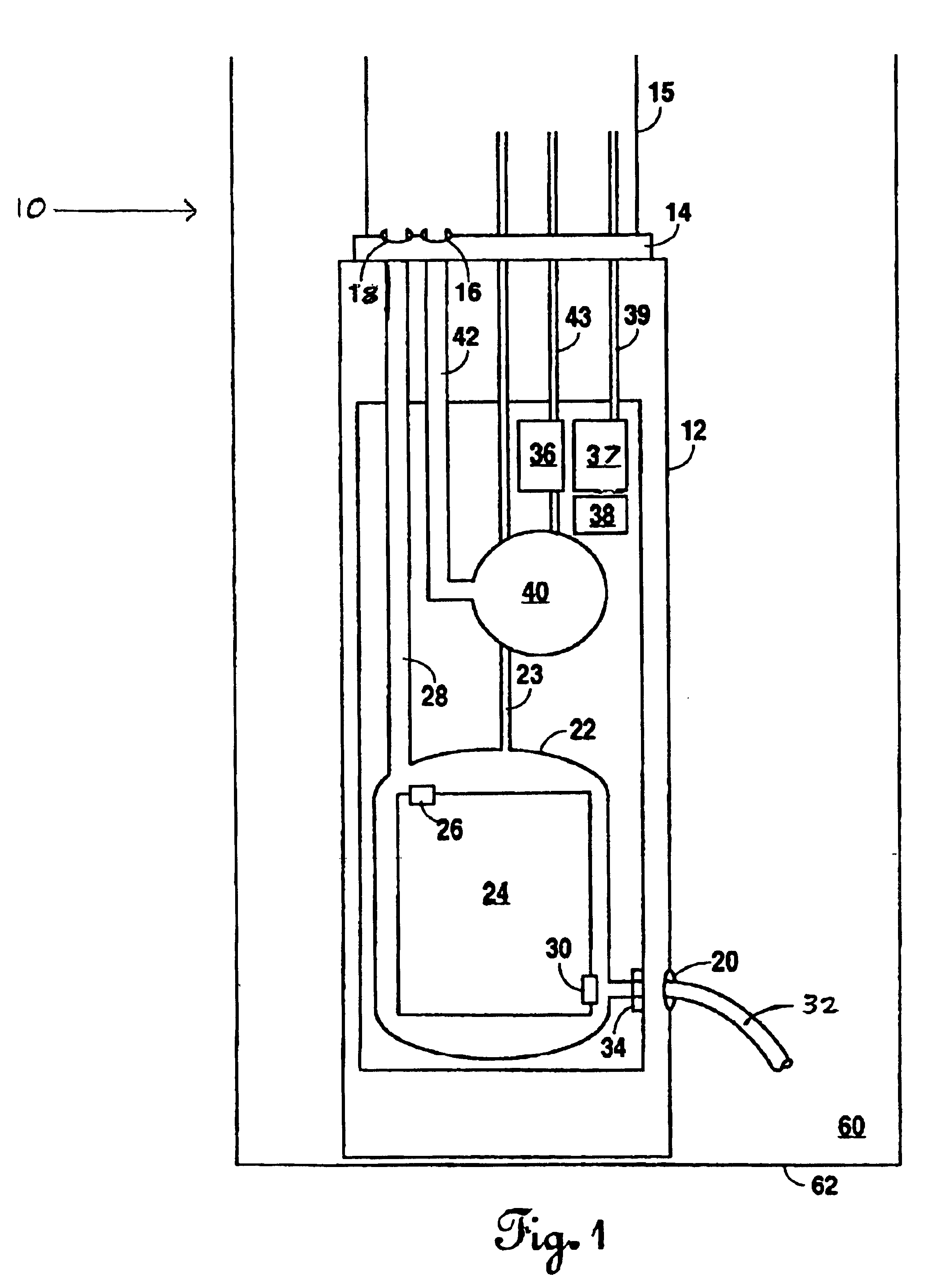
In the drawings and the description that follows, referring to FIG. 1, a preferred embodiment of a storage tank leak detection system according to the present invention is generally designated as system 10. An embodiment of the present invention is shown to include a vacuum-sealed canister 12, which houses and protects a plurality of mass measurement components and system control components. In the preferred embodiment, vacuum-sealed canister 12 is made of a substantially non-corrosive metal (aluminum, for example), however, any material that is corrosion resistant and offers sufficient protection to the components enclosed is adequate for use with the present invention. Canister 12 is directly immersed in storage tank 60 and rests on storage tank bottom surface 62. Canister 12 further contains vacuum seal nozzle 14 and transducer high side aperture 20. Vacuum seal nozzle 14 allows communication means to pass from the inside of the canister to the outside of the canister while maint...


PUM


Abstract

An intrinsically safe, precise, and cost effective storage tank leak detection system. Embodiments include a highly precise quartz crystal type pressure transducer, secured in a vacuum and held at a constant temperature. Said transducer is used in combination with data correction and regression techniques to yield a storage tank leak detection system with an extremely low leak detection threshold. The storage tank leak detection system is thought to be most useful for detecting very small leaks in very large storage tanks, most likely above ground storage tanks.

Description

BACKGROUND OF THE INVENTION1. Field of the InventionThe present invention is directed towards a method and apparatus for providing a safe, precise, and cost-effective storage tank leak detection system; and more particularly, to a method and apparatus wherein the containment integrity of a storage tank is determined by mass measurements of the stored product.2. Background InformationStorage tanks play a vital role in today's economy. The economy, on a global scale, depends on the proper function of these tanks as they are prevalent in several industries and virtually every geographical region in the world. In light of the vital role these storage tanks play, the integrity of the tanks is placed at a premium. That is, storage tank owners are willing to invest huge sums of money in both the maintenance and inspection of such tanks.These tanks come in all shapes and sizes, are found both below and above ground, and are used to store a wide-range of materials. Storage tank capacities ra...

Claims


Application Information

Patent Timeline
Patent Type & Authority Patents(United States)
IPC IPC(8): G01M3/32
CPCG01M3/3263
Inventor WOLFORD, JIMMYWOLFORD, BERNIELOCKERD, CLARKSLAUGHTER, RICKY
Owner MASS TECH
Why Eureka
Try Eureka