Ground fault detection system and method

a ground fault and detection system technology, applied in the field of ground fault protection, can solve problems such as electric shock, significant electrical safety concerns, and disabling or even destroying electronic equipmen

Inactive Publication Date: 2005-02-15
BAE SYSTEMS CONTROLS INC
View PDF14 Cites 82 Cited by
  • Summary
  • Abstract
  • Description
  • Claims
  • Application Information

AI Technical Summary

Benefits of technology

A power system for driving a load comprises a power distribution unit for distributing power via first and second power conductors to a corresponding at least one lead of the load according to a switching mechanism which selectively couples a given lead of the load to one of the first and second power conductors at a predetermined switching rate. The first and second power conductors are capacitively coupled to one another. A capacitor has a first terminal coupled to one of the first power conductor and second power conductor, and a second terminal coupled to the reference potential. A detector circuit is coupled to the first power conductor and is operative for sensing a change in voltage across the first power conductor with respect to the reference potential indicative of an unintended electrical path between the lead and the reference potential which causes the voltage developed across the first power conductor with respect to the reference potential to vary according to the magnitude of the power source, the detector generating a fault signal in response to the sensed voltage change exceeding a predetermined threshold. A controller responsive to the fault signal is operative to interrupt power from the first and second power conductors to the load, thereby tending to eliminate the time varying voltage developed at one of the first and second power conductors in response to the unintended electrical path between the lead and the reference potential, from being discharged across the capacitor.

Problems solved by technology

However, because of the high voltage requirements of its traction battery an electric or hybrid electric vehicle raises significant electrical safety concerns.
For example, unwanted electric current flow outside of the intended electric circuit flow (i.e. ground fault conditions) may cause significant damage to electronic components within a system (such as an HEV propulsion system), thereby disabling or even destroying the electronic equipment.
In addition, such ground fault conditions may result in an electric shock, which can have graver consequences when the shock is caused by contact with a high voltage traction battery system, as compared to a conventional, relatively low voltage automotive storage battery system.
While such isolated systems may minimize the likelihood of a significant electric shock to a person in the event of a short circuit or low impedance connection between a phase lead of a motor and the chassis (i.e a ground fault), certain electronic components typically in electrical communication with the positive and negative power conductors or rails that supply power to drive the motor, are subject to damage resulting from extreme voltage or current swings occurring on the positive and negative rails.
Further, while substantial work has been performed on detecting DC ground faults in high voltage DC systems, such DC ground fault detection schemes fail to detect ground faults on AC outputs of the DC system such as motors, generators or other loads.

Method used


Image

  • Ground fault detection system and method
  • Ground fault detection system and method
  • Ground fault detection system and method

Examples


Embodiment Construction

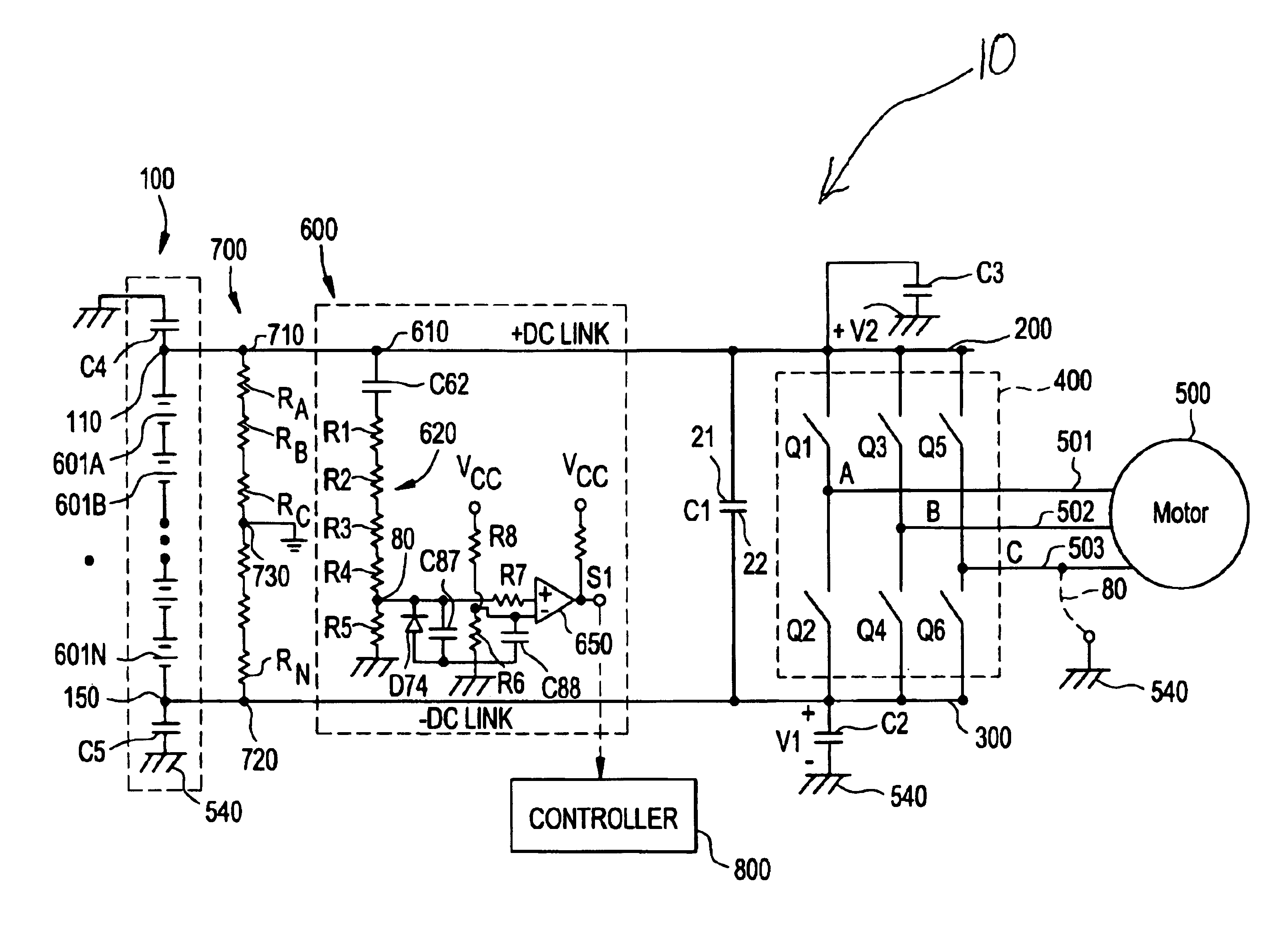
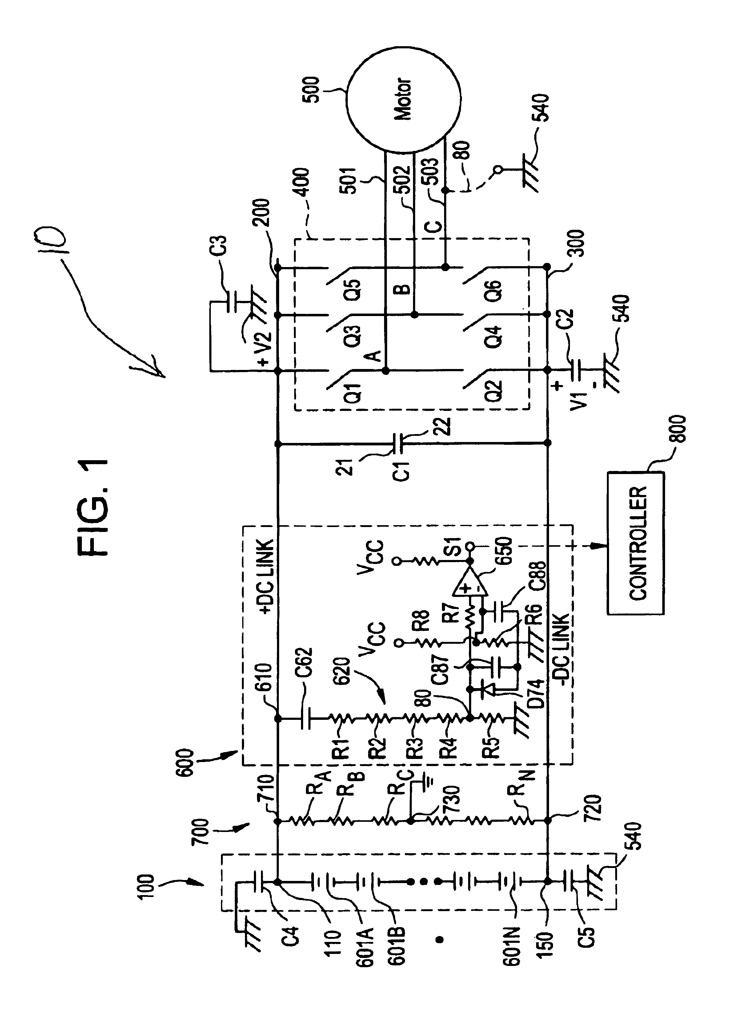
FIG. 1 shows an AC ground fault detector system 10 according to an aspect of the invention for sensing an AC signal indicative of an unintended electric path such as a short circuit or very low impedance connection between a load 500 such as an AC motor, and reference potential 540 such as chassis or ground. Power source 100 comprises a string of batteries 601A, 601B, . . . 601N for providing a high voltage (e.g. 600V) power source for driving motor 500 such as an electric traction motor. Terminal 110 of power source 100 is electrically coupled to motor 500 via a first power conductor 200, thereby providing a positive DC link with the motor, while terminal 150 is electrically coupled to motor 500 via second power conductor 300 for providing a negative DC link. A switching mechanism 400 such as an inverter is coupled between the first and second power conductors for alternately connecting a given phase lead 501, 502, 503 of motor 500 with one of the first and second power conductors ...


PUM


Abstract

In one embodiment, an AC ground fault detector system senses an AC signal indicative of an unintended electrical path between a load driven by a power source and a reference potential using a capacitively coupled circuit.

Description

RELATED APPLICATIONSNone.FIELD OF THE INVENTIONThe present invention relates to ground fault protection, and more particularly to an AC ground fault sensor system for detecting ground fault conditions.BACKGROUND OF THE INVENTIONElectrically powered automobiles are vehicles that do not depend on internal a combustion engines for propulsive power, but rather on relatively large electric traction batteries. The traction battery of an electric automobile is engaged with an electric traction motor for propelling the automobile, and the traction battery is rechargeable to permit repeated use of the traction battery.The skilled artisan will appreciate that a traction battery must have a relatively large capacity, and must deliver a relatively large amount of power, compared to a conventional 12 volt automobile storage battery. It is further understood that because power is directly proportional to battery voltage and system current, the high power delivery requirements which must be satisf...

Claims


Application Information

Patent Timeline
Patent Type & Authority Patents(United States)
IPC IPC(8): B60L3/00G01R31/02B60L3/04
CPCB60L3/0061B60L3/0069B60L3/04G01R31/025B60W10/08B60L2200/26B60W20/00G01R31/52
Inventor RODEN, GAREY GEORGECARRUTHERS, PETER ALEXANDER
Owner BAE SYSTEMS CONTROLS INC
Why Eureka
Try Eureka