Phase/frequency detector and phase lock loop circuit

a phase lock loop and detector technology, applied in oscillations comparator circuits, pulse automatic control, instruments, etc., can solve the problems of increasing lock times and complex state machines, and achieve the effect of significantly increasing cost and increasing lock tim

Active Publication Date: 2005-02-15
CIRRUS LOGIC INC
View PDF7 Cites 61 Cited by
  • Summary
  • Abstract
  • Description
  • Claims
  • Application Information

AI Technical Summary

Benefits of technology

The cycle slip detector arrangement may comprise a combination of PFD and cycle slip latching means with internal circuit structures arranged such that the cycle slip latching means is always reset from a particular input sig

Problems solved by technology

When cycle slips are occurring, the dynamic behaviour of the PLL is non-linear, and the behaviour can deviate away from that dictated

Method used


Image

  • Phase/frequency detector and phase lock loop circuit
  • Phase/frequency detector and phase lock loop circuit
  • Phase/frequency detector and phase lock loop circuit

Examples


Embodiment Construction

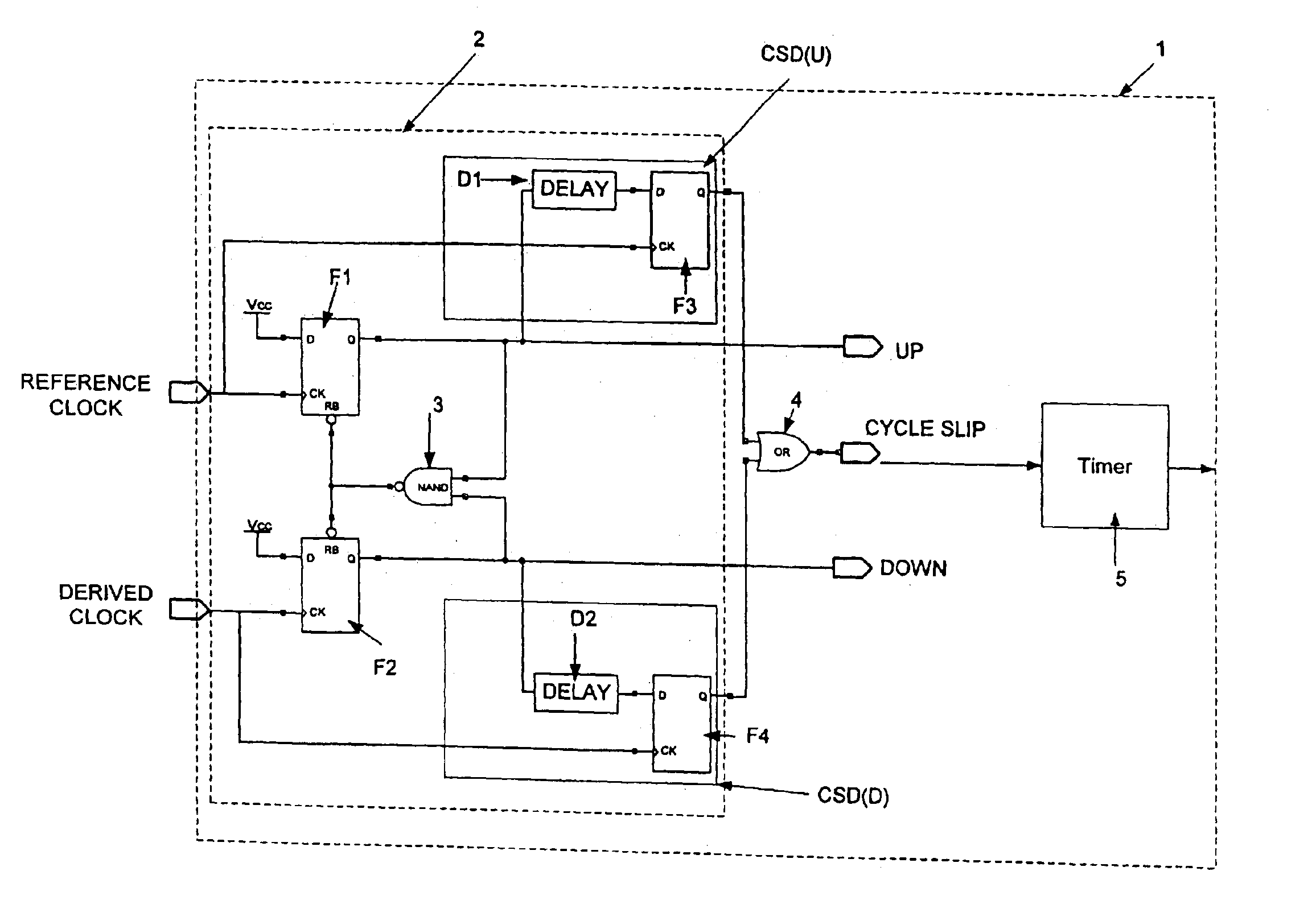
FIG. 4 shows a PLL lock detector 1 according to an embodiment and comprising a cycle slip detector 2 and a timer circuit 5. The cycle slip detector 2 comprises a phase and frequency detector (PFD) having two input or PFD latch means F1 and F2 which are coupled respectively to a reference clock signal (REF) and a derived clock signal (DER) such as the output of a VCO, and a NAND gate 3. The outputs of the input latches F1 and F2 are coupled respectively to UP and DOWN cycle slip detector circuits (CSD(U) and CSD(D)) which each comprises a delay element D1 or D2 and an output or cycle slip latch means F3 or F4. The CK input of each output latch F3 and F4 is coupled to the respective clock input (reference or derived respectively).

The reference clock input is coupled to the CK input of a PFD latch F1, and the derived clock input to the CK input of other PFD latch F2. The D inputs of these latches F1 and F2 are coupled to a reference voltage such as the positive supply voltage Vcc. The ...


PUM


Abstract

The present invention relates to cycle slip detectors for phase and frequency detectors (PFD) and to lock detectors for phase lock loop (PLL) circuits. The present invention provides a cycle slip detector circuit for use with a phase and frequency detector circuit having first and second signal inputs, and arranged to provide first and second PLL control signal outputs responsive to clock edges in the first and second input signals respectively; the cycle slip detector circuit comprising: means for determining a cycle slip between said input signals by determining when a delayed output signal coincides with a respective input signal.

Description

FIELD OF THE INVENTIONThe present invention relates to cycle slip detectors for phase and frequency detectors (PFD) and to lock detectors for phase lock loop (PLL) circuits.BACKGROUND OF THE INVENTIONPhase lock loops (PLL) are well-known circuits that are used to lock a locally generated signal such as a clock signal to an external or reference signal. This might be applied for example in telecommunications receiver equipment or digital audio equipment which receives a reference signal and needs to generate a local clock signal whose frequency and phase are related to the received reference signal (a condition known as lock) in order to properly receive incoming information signals. A schematic of a PLL is shown in FIG. 1 and comprises a phase and frequency detector (PFD), a charge pump (CP), a loop filter (LF) and an oscillator (VCO) in a feedback loop. The detector (PFD) detects the frequency or phase difference between the signal output by the oscillator (VCO) (the derived clock)...

Claims


Application Information

Patent Timeline
IPC IPC(8): H03L7/089H03L7/10H03L7/095H03L7/08
CPCH03L7/0891H03L7/10H03L7/095Y10S331/02H03L7/101
Inventor LESSO, PAUL
Owner CIRRUS LOGIC INC
Why Eureka
Try Eureka