Group velocity dispersion measuring device and group velocity dispersion measuring method
- Summary
- Abstract
- Description
- Claims
- Application Information
AI Technical Summary
Benefits of technology
Problems solved by technology
Method used
Image
Examples
fourth embodiment
FIG. 12 is a structural view of chirped light generating means according to a
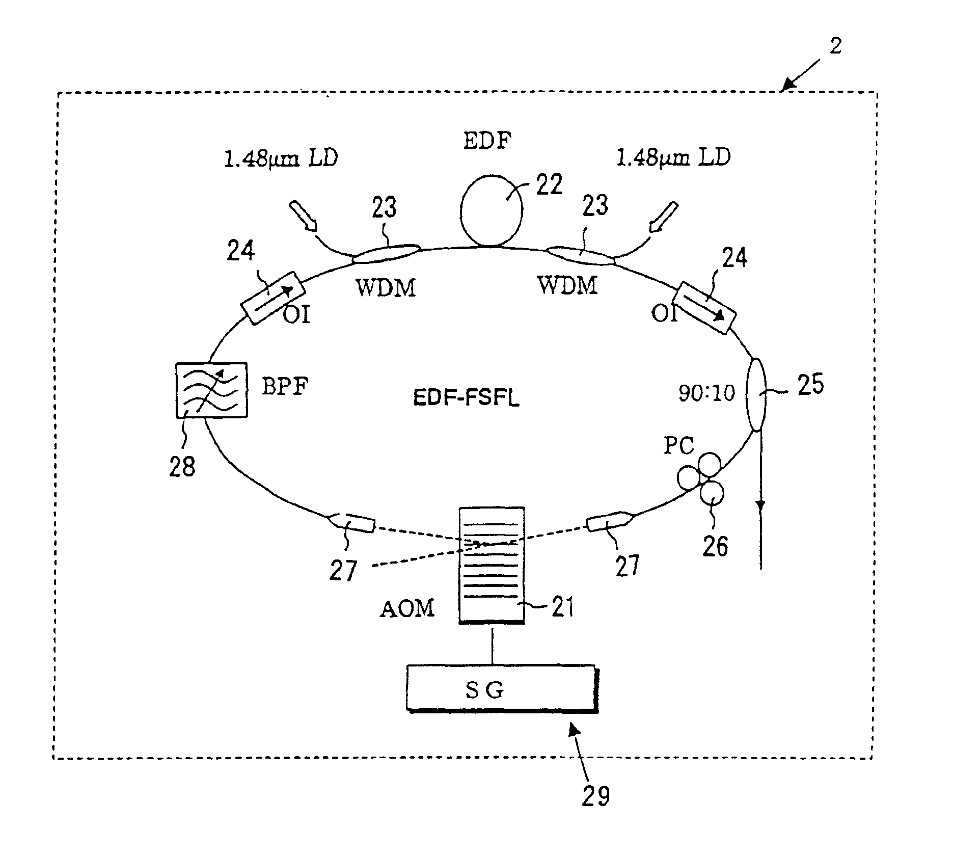
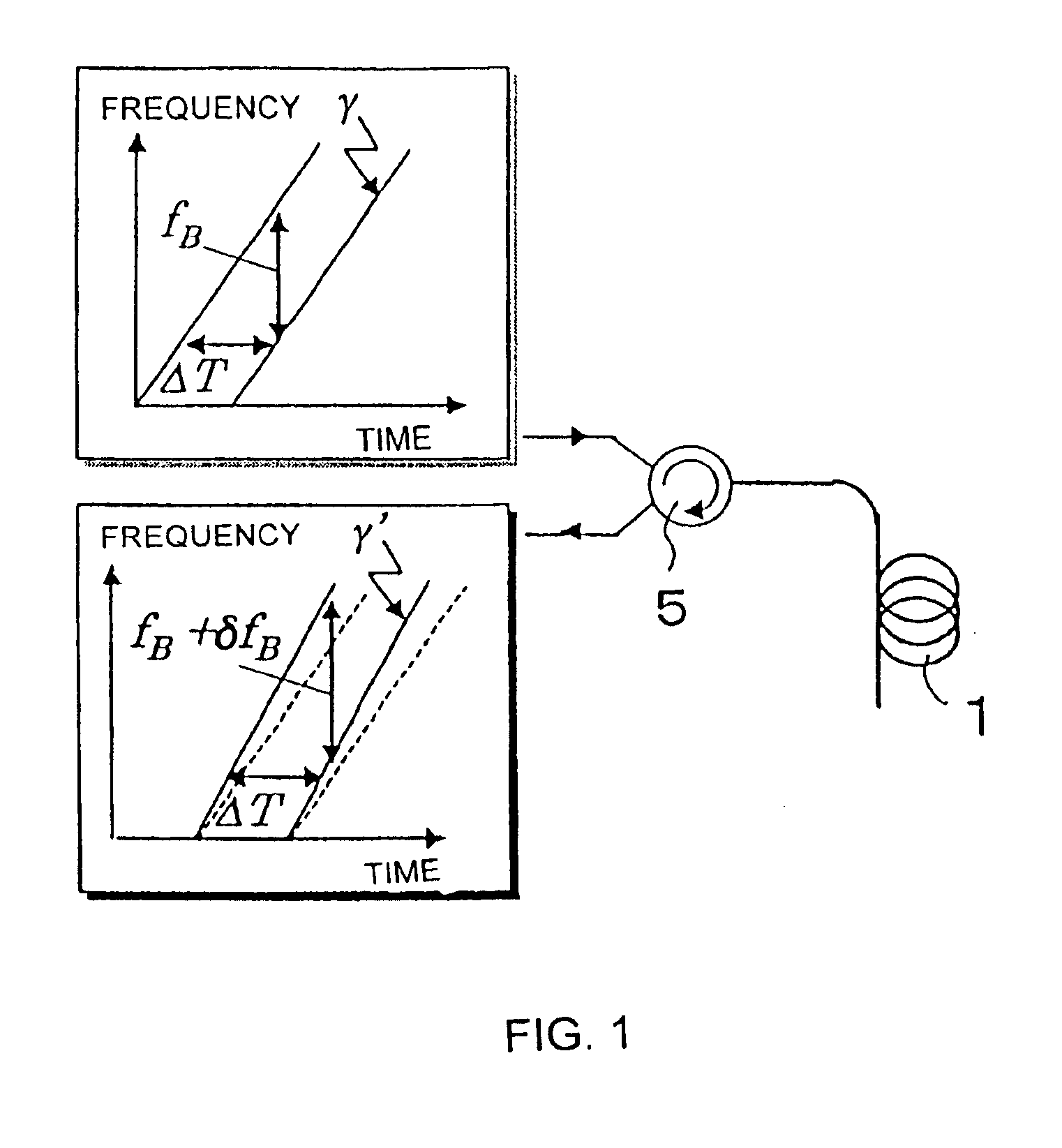
Chirped light generating means 400 includes a frequency-chirped light source 401 whose oscillated frequency shifts with time, and an optical-branching coupler 402 for branching light emitted from the frequency-chirped light source 401, applying a delay 403 to one light beam, and coupling that light beam with the other light beam. With such a configuration, at least two frequency-chirped light beams can be generated.
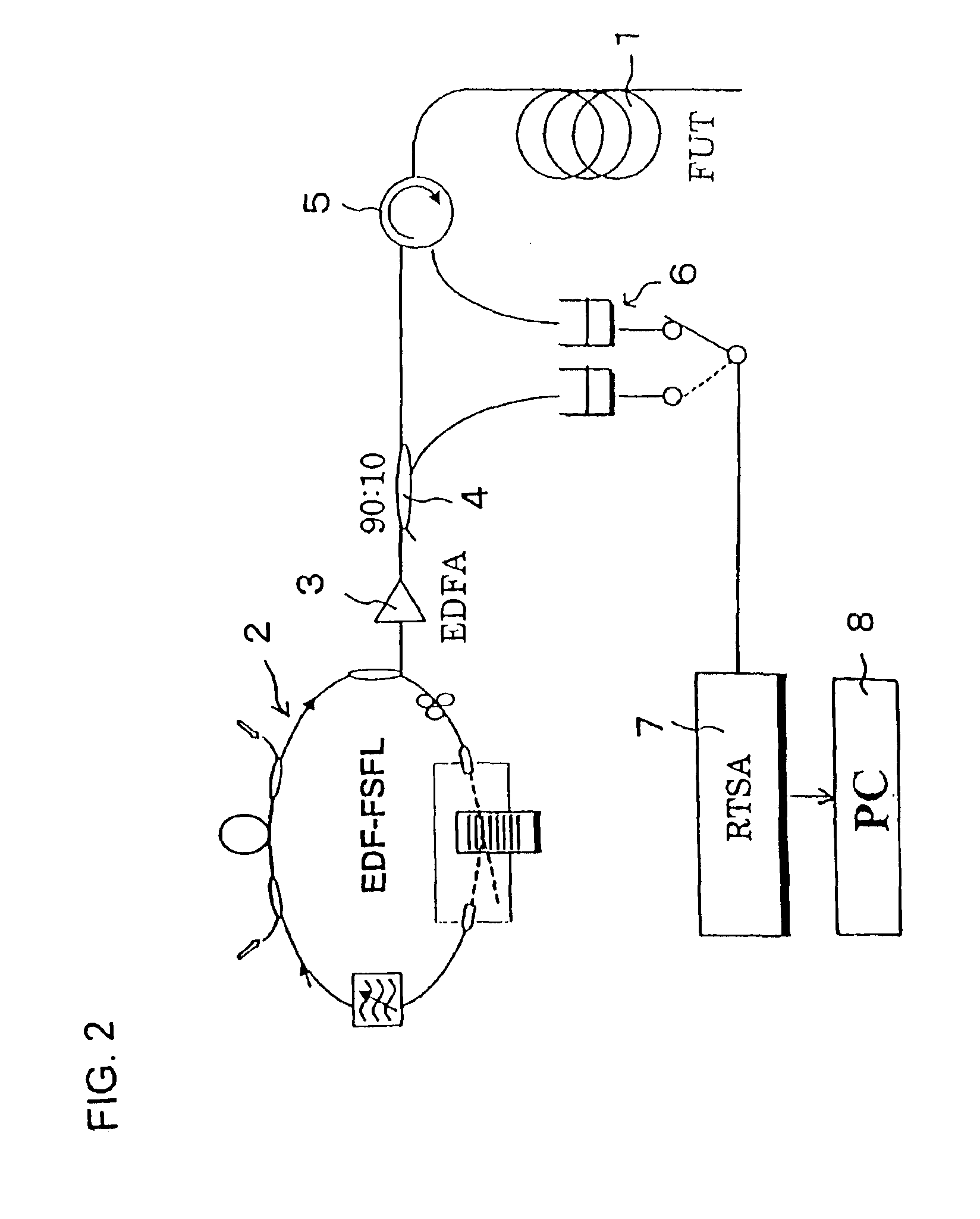
Note that, any appropriate light source whose oscillated frequency shifts with time can be employed as the frequency-chirped light source. Further, instead of measurement being performed at the input side of the optical fiber under test 1, as described above, a measurement system may be provided at the output side.
PUM
 Abstract
Description
Claims
Application Information
 - R&D
- Intellectual Property
- Life Sciences
- Materials
- Tech Scout
- Unparalleled Data Quality
- Higher Quality Content
- 60% Fewer Hallucinations
Browse by: Latest US Patents, China's latest patents, Technical Efficacy Thesaurus, Application Domain, Technology Topic, Popular Technical Reports.
© 2025 PatSnap. All rights reserved.Legal|Privacy policy|Modern Slavery Act Transparency Statement|Sitemap|About US| Contact US: help@patsnap.com


