Fuel pump and direct fuel injection engine

Inactive Publication Date: 2005-03-01
HITACHI LTD
View PDF11 Cites 33 Cited by
  • Summary
  • Abstract
  • Description
  • Claims
  • Application Information

AI Technical Summary

Benefits of technology

[0040]Further, in regard to each of the sliding parts in the fuel (gasoline), the wearing resistance is improved by performing the surface treatment.
[0041]A diffusion surface treated layer or a corrosion-resistant and wearing-resistant hardened film is formed as the surface treated layer. In regard to the diffusion surface treated layer, as the nitriding group layers increasing the hardness by diffusing mainly nitrogen to precipitate fine grain nitrates there are the nitrided layer, the carbonitrided layer, the soft nitrided layer and the salt-bath nitrided layer. Further, the carburization treatment for obtaining high hardness by diffusing carbon at a high temperature range and then performing quench-heat treatment may be also employed. In the nitriding group layer, nitride producing elements are formed into nitrides to increase the hardness higher than the base material, and to make the property difficult to be seized, and to improve the resistances of the base material against friction and wear. Further, the nitrided layer has a property hardly to be separated even under a high surface pressing

Problems solved by technology

Since the film is generally formed under a pressure of several Pa by the plasma CVD, the plasma CVD method is better than the PVD method in treatment of a narrow portion due to the mean free path (traveling distance of a particle in a gas atmosphere without collision), but the difficulty of treatment is nearly equal to each other.
On the other hand, since chlorine of a component of a feed gas is mixed into the film, there is a problem in that the film properties such as corrosion resistance, wear resistance, hardness and the like are degraded.
It is described that the effect of the TiCN film as a wear resistant film is insufficient when the thickness is thinner than 2 μm, a

Method used


Image

  • Fuel pump and direct fuel injection engine
  • Fuel pump and direct fuel injection engine
  • Fuel pump and direct fuel injection engine

Examples


embodiment 1

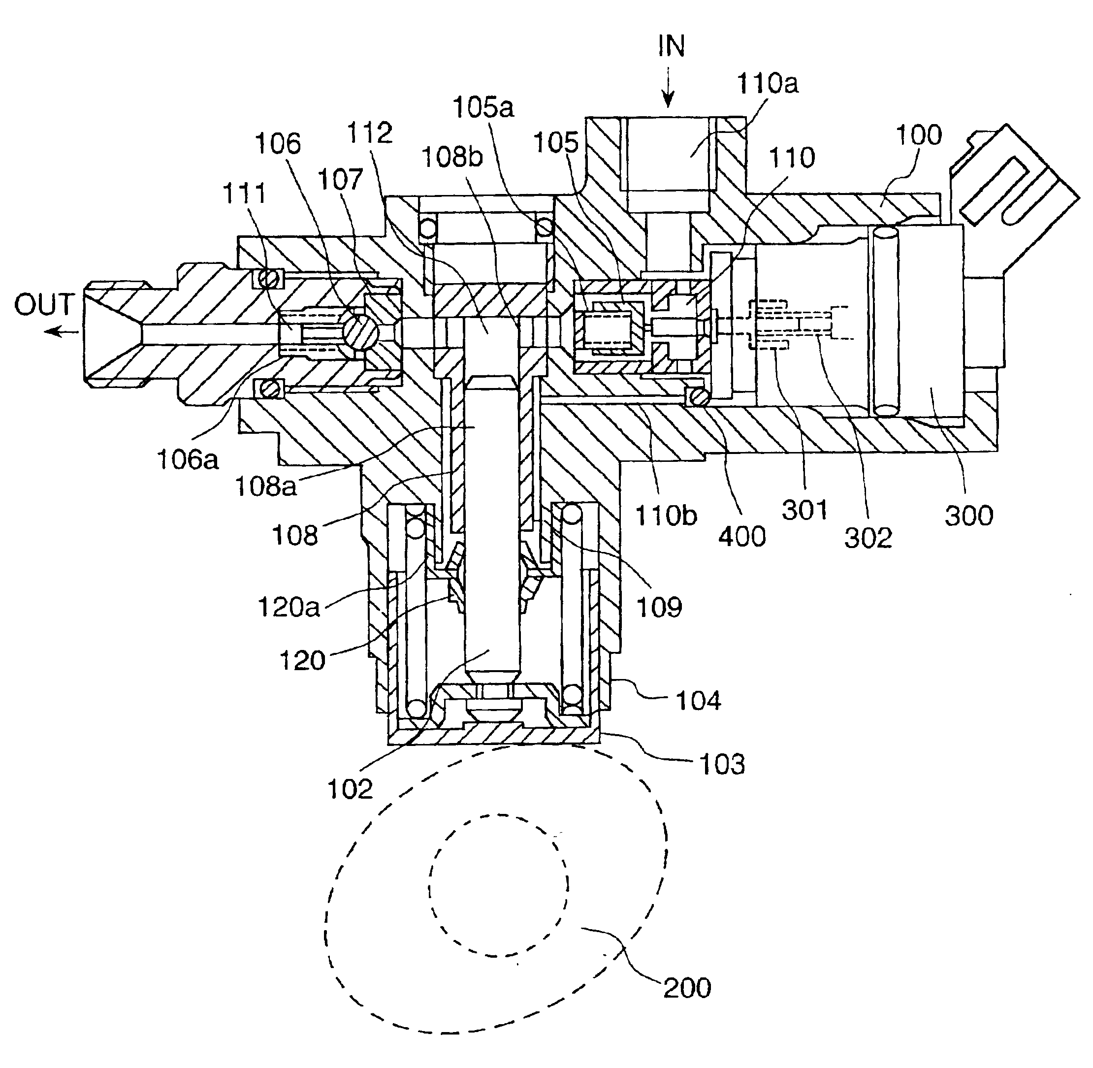
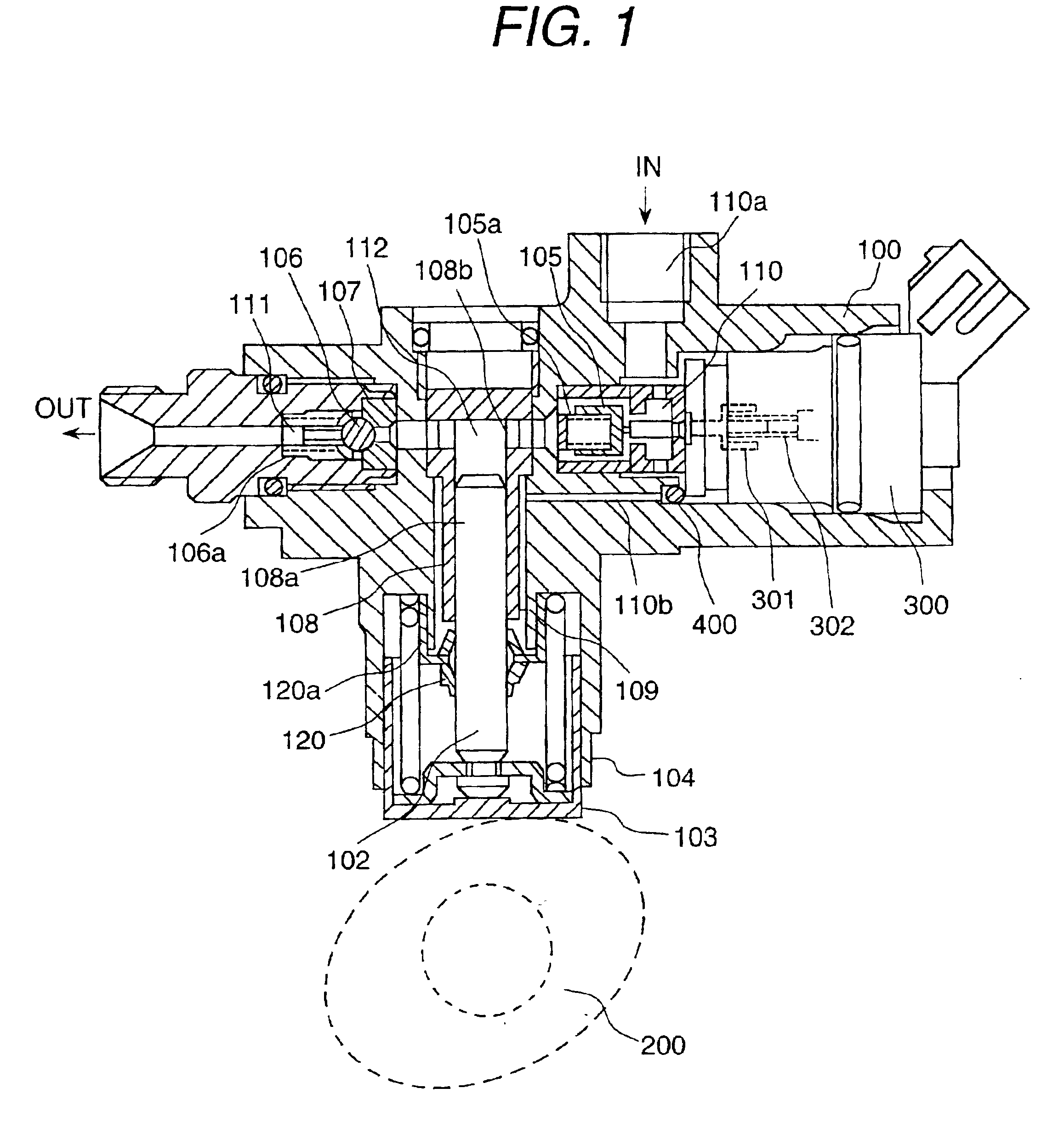
[0068]The present embodiment relates to a radial plunger fuel pump (single cylinder type). The radial plunger fuel pump comprises a shaft for transmitting a driving force of an engine; a driving cam for converting rotation motion of the shaft to oscillation motion; a plunger for converting the rotation motion of the driving cam to reciprocal motion inside cylinder through a slipper; and a cylinder bore combined with the plunger to suck and deliver fuel, wherein a nitrided layer, a carburization quenched layer or a carburization quenched layer coated with a highly hard carbon group film is formed on at least one of surfaces of the above-described mechanism portions sliding by being lubricated by fuel and members of pump portions.

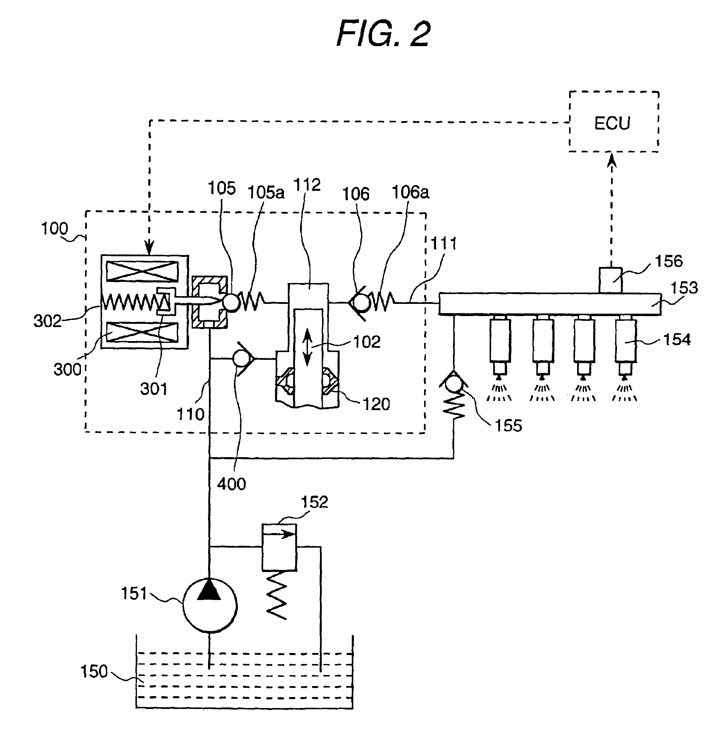
[0069]FIG. 1 and FIG. 2 show the details of the radial plunger pump in accordance with the present embodiment. FIG. 1 is a vertical cross-sectional view, and FIG. 2 is a diagram showing the construction of a fuel injection system using the present embodiment....

embodiment 2

[0121]FIG. 12 is an enlarged cross-sectional view showing details of a part of the radial plunger pump of FIG. 1. Description will be made on another embodiment when a sliding mechanism portion requiring the corrosion resistance and the wearing resistance is constructed in the radial plunger pump of FIG. 1. FIG. 12 shows the embodiment in regard to a sliding portion between a driving cam rotated by transmitting a driving force of the engine to the cam and a lifter for converting the rotating motion of the driving cam to the reciprocal motion of the plunger.

[0122]There is a possibility that lubrication between the driving cam and the lifter portion is insufficient because engine oil in a spray state may be supplied to the portion. Since the driving cam moves at a high speed equal to or ½ of the rotation speed of the engine, the relative sliding speed on the lifter surface becomes +30 m / s to −4 m / s. Further, the driving cam is in contact with the lifter portion at a pressure above 500...

embodiment 3

[0126]FIG. 13 is a cross-sectional view showing an example of an axial plunger fuel pump of a slant plate type (three cylinder type). The slant plate type axial plunger pump comprises a shaft 1 for transmitting a driving force from the external to the inside of the housing; a slant plate 9 for converting rotating motion to oscillating motion through the shaft; plungers for converting the rotating motion of the slant plate to reciprocal motion through a slipper 10; and cylinder bores 13 for sucking and delivering fuel, each of the cylinder bores being coupled with each of the plungers 11. The smooth surfaces of the slant plate 9 and the slipper 10 lubricated by a lubricating oil (engine oil) are designed so as to use a material selected by considering seizing resistance in a range of high slipping speed (high peripheral speed), and the spherical portions of the slipper 10 and the plunger 11 are designed so as to use a material selected by considering wear resistance in line contact u...


PUM

PropertyMeasurementUnit
Thicknessaaaaaaaaaa
Wear resistanceaaaaaaaaaa
Ratioaaaaaaaaaa

Abstract

A fuel pump, of which sliding mechanism parts in its fuel chamber have good wear resistance under a severe environment, and a direct fuel injection engine using the fuel pump are provided.
In a fuel pump for pressurizing and delivering fuel to a fuel injector of a vehicle engine, at least one of sliding surfaces of a slant plate, a slipper and a plunger sliding in a lubricating oil and at least one of sliding surfaces of sliding members of a plunger and a cylinder contacting with and sliding on each other through the fuel are formed of a hardened layer composed of any one of a nitrided layer, a carburization quenched layer and a carbonitrided layer, or coated with a high corrosion resistant and hard metal compound layer over the hardened layer.

Description

BACKGROUND OF THE INVENTION[0003]This application claims the priority of Application No. 2001-345505, filed Nov. 12, 2001, in, the disclosure of which is expressly incorporated by reference herein.[0004]The present invention relates to a fuel pump for supplying fuel in an internal combustion engine and a direct fuel injection engine, and particularly to a fuel pump used for a high pressure pump of a fuel injector for a direct fuel injection engine of a vehicle in which fuel is directly injected into a combustion chamber from the fuel injector attached to the combustion chamber of the vehicle engine, and to the direct fuel injection engine.[0005]In general, an in-cylinder direct fuel injection device requires a high pressure pump capable of supplying gasoline into cylinders of an internal combustion engine with a high pressure above 3 MPa because it is necessary to directly inject gasoline into the cylinders even at the compression stroke.[0006]One type of the high pressure pumps is ...

Claims


Application Information

Patent Timeline
IPC IPC(8): C23C8/80C23C28/00F02M63/02F02M59/10F02M59/00F02M59/36F02M59/20F02M59/44F02M63/00F04B1/04F04B1/12F04B1/14F04B1/00C22C38/00F02M37/06C23C28/04F02M59/04F04B9/04F04B53/00
CPCC23C8/80C23C28/00C23C28/048F02M59/102F02M59/366F02M59/445F02M63/0225F04B1/0408F04B1/0413F04B1/0421F04B1/0426F04B1/143F04B1/146C23C28/044F02M2200/02F05C2253/12
Inventor YAMAGUCHI, SHIZUKABABA, NOBORUNAGAYAMA, TOSHIAKITERAKADO, KATSUYOSHIKAGIYAMA, ARATAMACHIMURA, HIDEKIYAMADA, HIROYUKITAKAHASHI, YUKIOKOTAKI, MASAYOSHIOJIMA, KAZUO
Owner HITACHI LTD
Why Eureka
Try Eureka