Optical transmission module

a technology of optical transmission module and optical transmission module, which is applied in the direction of optics, optical elements, instruments, etc., can solve the problems of difficult manufacturing of optical transmission module, inability to find suitable compact means for collectively connecting multicore core optical fibers to optical transmission modules, and large size of optical transmission modules. achieve the effect of reducing size and weigh

Inactive Publication Date: 2005-03-01
SUMITOMO ELECTRIC IND LTD
View PDF7 Cites 10 Cited by
  • Summary
  • Abstract
  • Description
  • Claims
  • Application Information

AI Technical Summary

Benefits of technology

Accordingly, it is an object of the present invention to prov

Problems solved by technology

However, the above-described prior arts raise a problem in that there is no appropriate compact means for collectively connecting multicore cores optical fibers to optical transmission modules.
On the other hand, because the optical transmission module has an optical system in which the optical axis of the optical emitting device and that of the optical receiving device are orthogonal to each other, the manufacturing thereof is difficult, and the optical trans

Method used


Image

  • Optical transmission module
  • Optical transmission module
  • Optical transmission module

Examples


first embodiment

Here, the present invention will be described taking, as an example, an optical transmission module connected to a 4-core optical fiber ribbon in which an MT connector is formed at an end portion thereof.

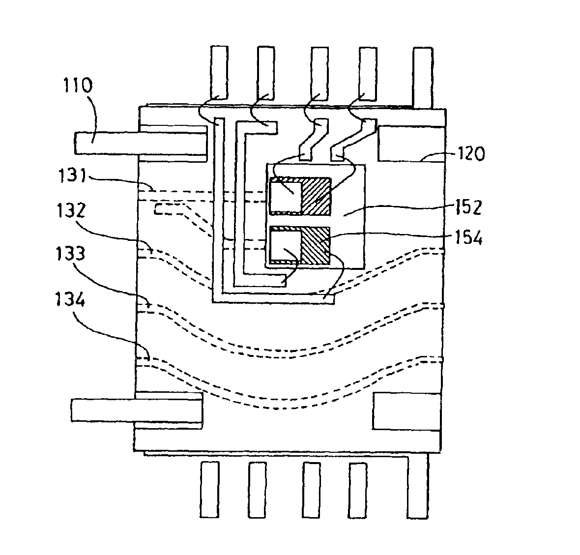
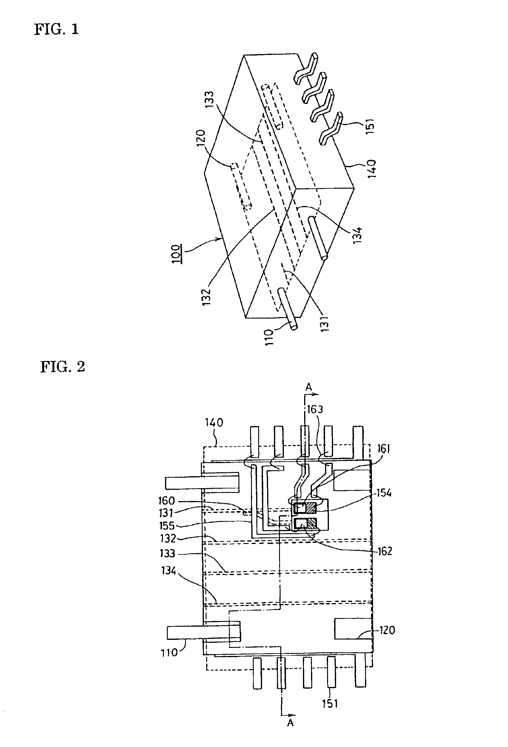
As shown in FIG. 1, in this module 100, one end face thereof has a pair of guide pins 110 projected therethrough, and the other end face thereof has guide holes 120 into which the guide pins of a post-stage module are to be inserted. The end faces of four light waveguides 131 to 134 are exposed between the guide pins 110 on the one end face, while the end faces of three light waveguides 132 to 134 are exposed between the guide holes 120 in the other end face. The entire module 100 is covered with resin mold 140 formed into a rectangular parallelepiped shape, and a plurality of leads 151 are projected through opposite side surfaces. This module 100 is a first-stage module. At stages succeeding to the first stage, modules are sequentially connected in a multistage manner, as described...

second embodiment

Next, a description will be made of a module according to the present invention that is usable even when the pitch of the cores of the 4-core fiber ribbon to be collectively connected is narrow. In this module, the parallel pitch of the light waveguides is set to be 250 μm in alignment with the pitch of the optical fiber.

FIG. 7 is a perspective plan view showing the first-stage optical transmission module. Here, the Si platform 152 is depicted in an enlarged form.

In this module also, only one light waveguide 131 of the four cores (four waveguides) is formed into a linear shape, and is connected to the optical communication facility section, as in the case of the first embodiment. The remaining light waveguides 132 to 134 are formed into an arcuate shape so as to detour around the optical communication facility section.

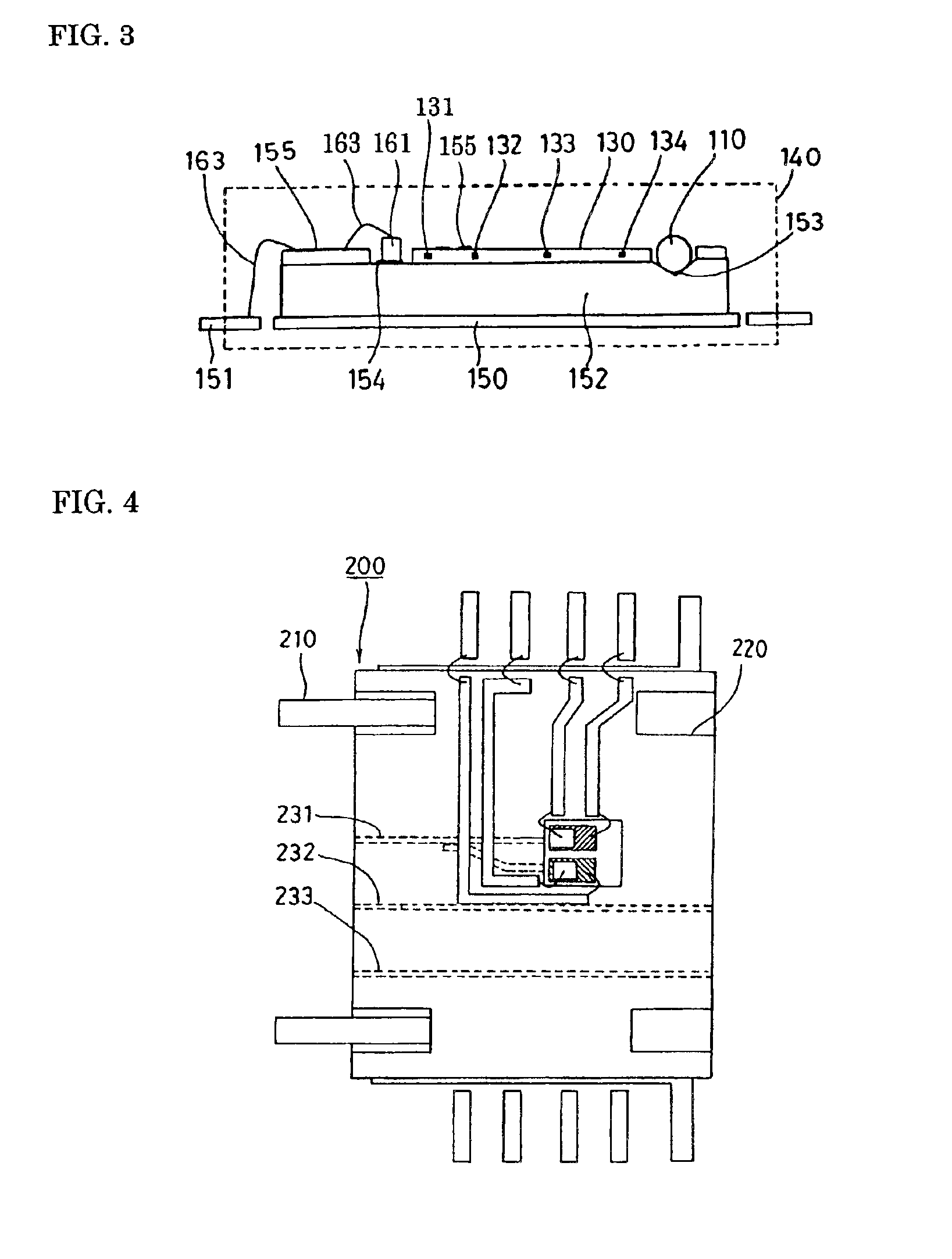
As is evident from FIG. 3 showing the first embodiment, the optical communication facility section is constructed such that the metallized pattern 154 are formed on th...

third embodiment

Next, an optical transmission module of the present invention in which lead pins are also exposed on an end face of the module is shown in FIG. 8. FIG. 8 is a perspective plan view showing the optical transmission module of the present invention in which lead pins are also exposed on an end face of the module. FIG. 9 is a plan view showing the arrangement of the lead pins of an optical transmission module of the present invention in which the lead pins are led out to the end face of the module. FIG. 10 is a longitudinal sectional view illustrating the module shown in FIG. 8.

This module has a construction in which lead pins 156 are connected to the leads 151 that are connected to the optical communication facility section through the Au lines, and in which the lead pins 156 are led out, being curved on the way, to the first end face side of the module. The other lead pins 157, which are not connected to the optical communication facility section, are each arranged linearly such that ...


PUM


Abstract

An optical transmission module includes plural optical transmission means (optical waveguides) whose end portions are exposed on a first end face thereof, and at least one of an optical transmitting section and an optical receiving section to each of which some of the optical transmission means are optically coupled. The remaining optical transmission means are exposed on a second end face opposed to the first end face. Only some of the plural optical transmission means are designed to have a communication facility at some position in the longitudinal direction thereof, while the remaining optical transmission means are designed to have the communication facility by being connected to post-stage optical transmission modules in the longitudinal direction. By multistage-connecting these optical transmission modules, plural optical transmission means and optical transmission modules can be collectively connected at a narrow frontage.

Description

BACKGROUND OF THE INVENTION1. Field of the InventionThe present invention relates to an optical transmission module. Particularly, the present invention relates to optical transmission module that can be reduced in size and weight and to which a multicore optical fiber ribbon or the like can be connected.2. Description of the Related ArtPrior Art 1When bi-directional communication is to be performed with a plurality of optical fibers, a system shown in FIG. 13 is constructed. This system is an optical fiber network in which optical fibers 330 are led into subscribers 320 from an optical communication equipment 310 provided in a central station 300. The optical communication equipment 310 is constituted of an assembly of a multitude of optical transmission modules 340.One example of this optical transmission module is illustrated in FIG. 14. In this module 400, a light emitting device 420 or a light receiving device 430 is optically coupled to each core of the multicore optical fiber...

Claims


Application Information

Patent Timeline
IPC IPC(8): G02B6/42G02B6/30H01L31/0232
CPCG02B6/4249G02B6/4246G02B6/30G02B6/4253G02B6/4265G02B6/4274
Inventor YAMABAYASHI, NAOYUKIKUHARA, YOSHIKI
Owner SUMITOMO ELECTRIC IND LTD
Why Eureka
Try Eureka