High resolution method for using time-of-flight mass spectrometers with orthogonal ion injection

a mass spectrometer and orthogonal ion technology, applied in mass spectrometers, particle separator tube details, separation processes, etc., can solve the problems of extremely restricted dynamic measurement range, large dynamic range reduction, and use of adcs,

Inactive Publication Date: 2005-03-01
BRUKER DALTONIK GMBH & CO KG
View PDF9 Cites 35 Cited by
  • Summary
  • Abstract
  • Description
  • Claims
  • Application Information

AI Technical Summary

Benefits of technology

The width of the ion signals, measured as the half-height signal width of the flight time, Δt, rises, in theory, linearly with the time of flight: Δt=t / 2R, where R is the mass resolution, R=m / Δm, theoretically constant across the spectrum. In practice, however, there is a further constant time (combined under Pythagorean addition) that arises from a widening of the signal in the detector, and which is particularly noticeable in the case of light, and therefore fast, ions. There is a clear relationship between the signal width and the specific mass, and this can be used for rough determination of the mass. The signal width, Δt, can be determined for signals that are well above the background noise to an accuracy of 5% (or better); this makes it very easy to determine whether an ion reached the detector in the first, second, third or even higher measurement cycle following the start pulse. This, in turn, yields the precise time of flight, and therefore the precise specific mass of the ions.

Problems solved by technology

This technique, however, only offers an extremely restricted dynamic measurement range, of the order of 1, and this can only be increased through summing a large number of individual spectra.
The use of ADCs, however, slightly reduces the mass resolution if good focusing achieves an ion beam signal width of about two nanoseconds.
The disadvantage of this solution, however, is that the dynamic range of the measurements is greatly reduced.
An insoluble dilemma is thus created: high mass resolution achieved by a long flight path means that an OTOF constructed according to conventional technology will always have either a low sensitivity or a low dynamic measurement range.

Method used


Image

  • High resolution method for using time-of-flight mass spectrometers with orthogonal ion injection
  • High resolution method for using time-of-flight mass spectrometers with orthogonal ion injection
  • High resolution method for using time-of-flight mass spectrometers with orthogonal ion injection

Examples


Embodiment Construction

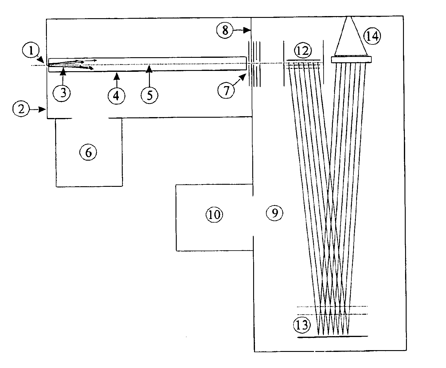
FIG. 1 is a schematic diagram of a time-of-flight mass spectrometer with orthogonal ion injection. A bundle (3) of ions with various initial energies and initial directions passes through an opening (1) in a vacuum chamber (2) and enters an ion guidance system (4) situated inside a gas-proof jacket. Damping gas enters the ion guidance system at the same time. The ions that enter are slowed by impacts with the gas. Because the ions in the ion guide system are subject to a pseudo-potential that is lowest at the axis (5), the ions accumulate at the axis (5). The ions spread out along the axis (5) as far as the end of the ion guide system (4). The gas in the ion guidance system is pumped out by the vacuum pump (6) attached to the vacuum chamber (2).

The drawing lens system (7) is located at the end of the ion guide system (4). An apertured diaphragm belonging to this drawing lens system is integrated into the wall (8) between the vacuum chamber (2) for the ion guidance system (4) and the...


PUM


Abstract

The invention relates to a time-of-flight mass spectrometer in which a fine beam of ions is injected orthogonally into a fast pulser that pulses the ions from the fine ion beam into the spectrometer's drift region for precise determination of mass. The invention consists in increasing the duty cycle of the ions through the use of a high pulser frequency, recording the data cyclically at the same frequency, and assigning slow ions that are only measured in one of the subsequent cycles to the correct initiating pulse through the form of their lines or line patterns.

Description

FIELD OF THE INVENTIONThe invention relates to a time-of-flight mass spectrometer for the precise determination of mass, in which a fine beam of ions is injected orthogonally into a fast pulser that pulses the ions in one section of the ion beam into the spectrometer's drift region.BACKGROUND OF THE INVENTIONThe best choice of mass spectrometer for measuring the mass of large molecules, as undertaken particularly in biochemistry, is a time-of-flight mass spectrometer because it does not suffer from the limited mass range of other mass spectrometers. Time-of-flight mass spectrometers are frequently abbreviated to TOF or TOF-MS.Two different types of time-of-flight mass spectrometer have been developed. The first type comprises time-of-flight mass spectrometers for measuring ions which are generated in pulses in a tiny volume and accelerated axially into the flight path, for example with ionization by matrix-assisted laser desorption, MALDI for short, a method of ionization suitable f...

Claims


Application Information

Patent Timeline
Patent Type & Authority Patents(United States)
IPC IPC(8): H01J49/34H01J49/40H01J49/02
CPCH01J49/0031H01J49/401
Inventor FRANZEN, JOCHEN
Owner BRUKER DALTONIK GMBH & CO KG
Why Eureka
Try Eureka