Package of lightemitting diode with protective element

a technology of protection element and light-emitting diode, which is applied in the field of light-emitting diodes, can solve the problems of increasing the difficulty of alignment, destroying the light-emitting diode, and causing the electrostatic charge to continue to destroy the light-emitting diod

Inactive Publication Date: 2005-03-01
EPISTAR CORP
View PDF7 Cites 59 Cited by
  • Summary
  • Abstract
  • Description
  • Claims
  • Application Information

AI Technical Summary

Problems solved by technology

However, the P / N junction is very close to the surface, and thus is readily destroyed by the electrostatic charges.
Under such situation, if it happens that the man unintentionally touches one of the diode pins, even a minute current may still destroy the light-emitting diode, which is typically operate at the range of 1-4 volt.
However, each of them though solve some disadvantages present in the prior art but new issues are associated with the newly method.
However, to tell about the package process, several issues are found.
Thus for a chip is flipped, the difficulty of alignment is drastically increased while the p-electrode 5 of the and n-electrode of the light-emitting diode, respectively, aligned with such miniature bumps 12 and 11 on the n-electrode 8 and the p-electrode 7 of Zener diode It will be detrimental to the mass produce and the yield.
Still, the heat dissipation can only slowly dissipate through the light-emitting diode itself and part of them from the silicon diode.
Therefore the package techniques provided by Inoue still have room to improve.
It will increase fabrication cost compared with those Zener diode, which has p-electrode and n-electrode on the different sides.
Although the benefits as depicted above, some fatal problems are associated with the structure of the second embodiment: (1) the position height of the flange 62 and the bottom 61 of the reflector are different, and both of them are required to have a silver paste layer welded, and thus the welding stud machine would be much expensive than those for just one point stud.
Furthermore, the area of the flange 62 is far less than the area of the bottom 61 of the reflector, As a result, the difficulty for pasting the silver paste thereon.
Therefore, it's unpractical technique unless the silver paste-welding machine is re-designed or re-equipped.

Method used


Image

  • Package of lightemitting diode with protective element
  • Package of lightemitting diode with protective element
  • Package of lightemitting diode with protective element

Examples


Embodiment Construction

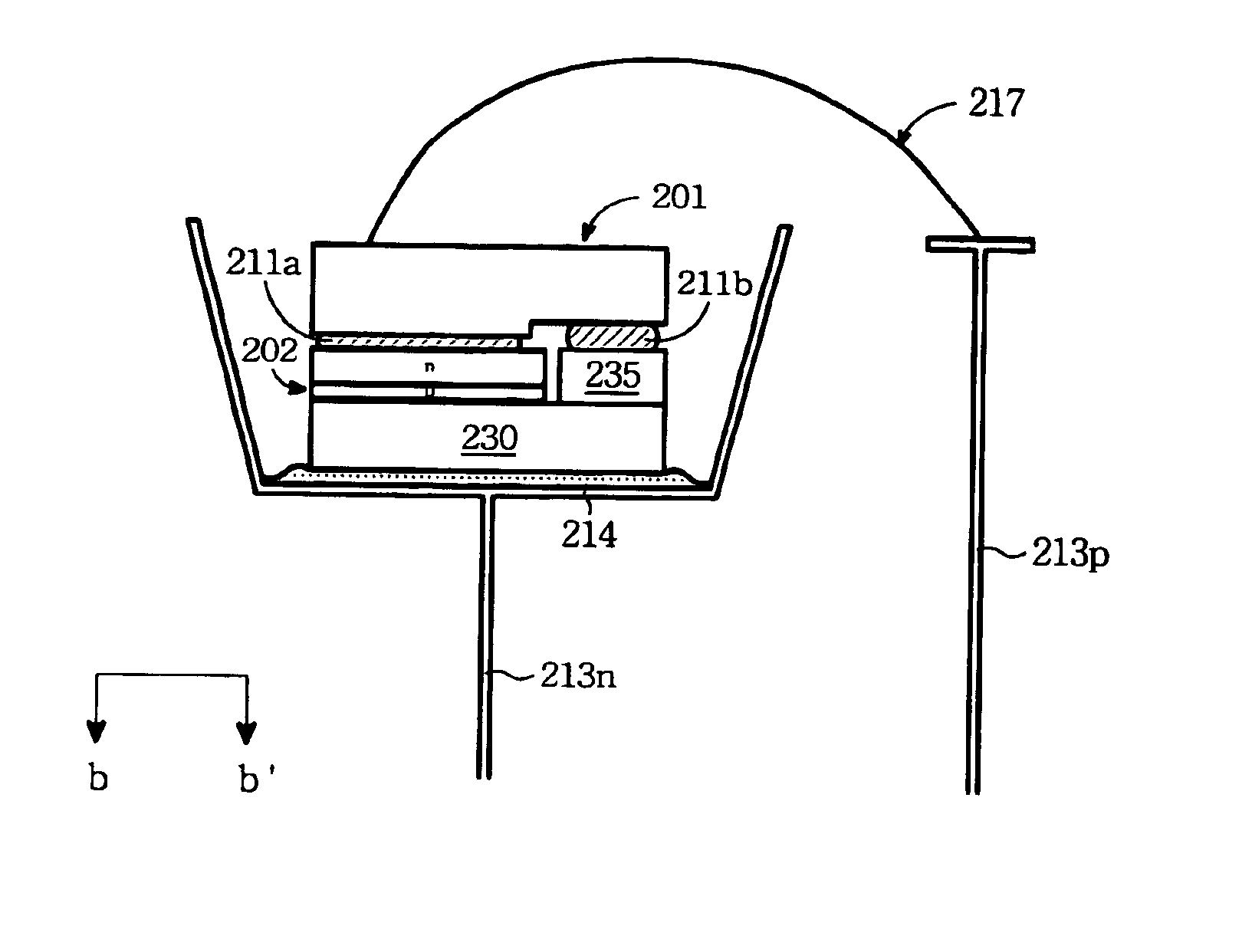
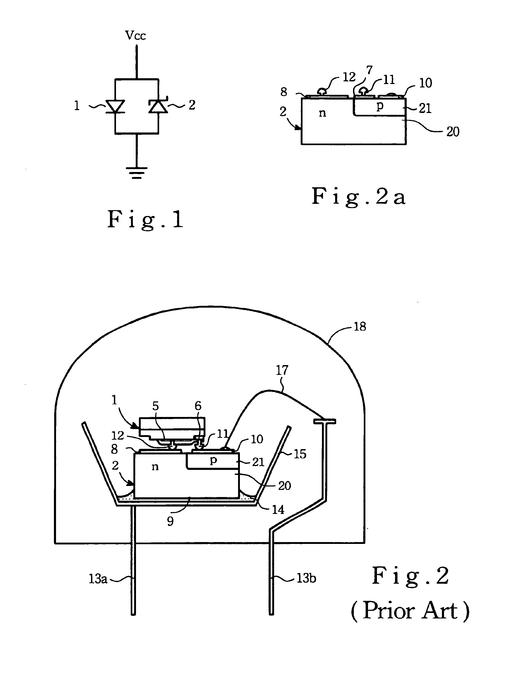
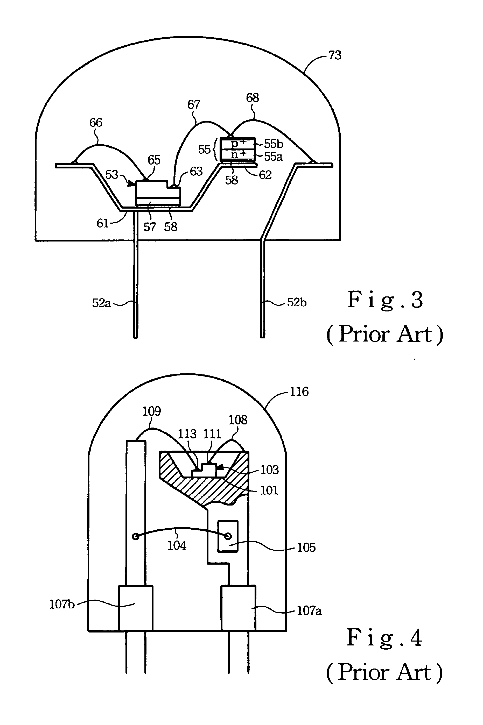
As forgoing prior art depicted for the light-emitting diode with protective diode, while a new package structure is proposed to solve the issues of the prior art thereof, however, a new problem is often generated accompanying with the newly proposed method. Although light intensity of the flip-chip package for the light-emitting diode with the p-electrode and the n-electrode on the same side is the best among all because it without the light degraded by the shielding of the electrode, it has the problem of alignment for Zener diode and the LED each other and thus it is not suitable to mass produce In addition, the manufacture cost of Zener diode of p-electrode and the n-electrode on the one side is higher than those of on the two side. For examples, the package method as depicted in the second, the third, or the fourth preferred embodiment of the background of the invention, which are without the alignment problem and thus the yield anticipated to be increased, however, they general...


PUM


Abstract

A package structure of light-emitting diode with an electrostatic protective diode is disclosed. The structure has a light-emitting diode, an electrostatic protective diode, an electrical & heat conductive pad, and an electrical & heat conductive base substrate. The light-emitting diode is flipped and with its p-electrode and n-electrode, respectively, mounted on the n-electrode of the electrostatic protective diode and the electrical & heat conductive pad by conductive bumps. The latter two are separated themselves by a gap or an insulation layer and both of them are mounted on and electrically connected to the electrical & heat conductive base substrate. The structure is then through a bonding wire bonding to a bonding pad and the electrical & heat conductive base structure, respectively, connected to a positive and a negative terminal of a DC power to implement the electrical connection. The foregoing bonding pad is located on the exposed portion of n-electrode of the electrostatic protective diode.

Description

BACKGROUND OF THE INVENTION1. Field of the InventionThe present invention pertains to the light-emitting diode, and more particularly to the package of a light-emitting diode with an electrostatic protection element.2. Description of the Prior ArtGenerally, the light-emitting diode has the characteristics of: small volume, lower power consumption, longer life time, short response time, and with excellently monochromatic color. Generally, it is found to be applied in the home appliance, computer and its periphery, and communication products. Since, 1993 Nichia Chemical corp., successfully developed the gallium nitride (GaN), the blue light-emitting diode, which enables the light-emitting diode with fully colors to be realized and thus expands applications thereof to the fully color display, traffic light signal, traffic information panel and instrument panel in car, the braking light, and rear side-marker light. According to the research reports, the high intensity LED such as tour e...

Claims


Application Information

Patent Timeline
Patent Type & Authority Patents(United States)
IPC IPC(8): H01L25/16H01L33/20H01L33/32H01L33/60H01L33/62H01L33/64
CPCH01L25/167H01L2924/3011H01L2224/45144H01L2924/3025H01L2224/48091H01L2924/10253H01L2224/48137H01L2224/48247H01L2224/73265H01L2224/32245H01L2924/00H01L2924/00014H01L2924/00012
Inventor CHEN, TZER-PERNG
Owner EPISTAR CORP
Why Eureka
Try Eureka