Coil antenna/protection for ceramic metal halide lamps

a technology of ceramic metal halide and shielding, which is applied in the direction of transit-tube circuit elements, structural circuit elements, cathode-ray/electron beam tube circuit elements, etc., can solve the problems of limiting the lifetime of lamps to an unacceptable level, increasing the risk of premature failure, etc., and achieves excellent initial color consistency, excellent stability over life, and high luminous efficacy

Inactive Publication Date: 2005-03-01
KONINK PHILIPS ELECTRONICS NV
View PDF17 Cites 13 Cited by
  • Summary
  • Abstract
  • Description
  • Claims
  • Application Information

AI Technical Summary

Benefits of technology

Another object of the invention is to provide ceramic metal halide lamps of the Philips MasterColor® series that display excellent initial color consistency, superb stability over life (lumen maintenance >80%, color temperature shift <200K at 10,000 hrs), high luminous efficacy of >90 lumens / watt, a lifetime of about 20,000 hours, and power ranges of about 150 W to about 1000 W that use a metal coil wound around the arc tube for both ignition and containment.
Another object is to provide a way to mitigate the drawbacks and risks of failure discussed above.
Especially preferred are ceramic metal halide lamps that display excellent initial color consistency, superb stability over life (lumen maintenance >80%, color temperature shift <200K at 10,000 hrs), high luminous efficacy of >90 lumens / watt, a lifetime of about 20,000 hours, and power ranges of about 150 W to about 1000 W.

Problems solved by technology

The existing power range of such lamps is from 20 W to 150 W. The relatively narrow power range makes these products only suitable for the applications requiring low power installations, such as most indoor low-ceiling retail spaces.
Simply scaling up the dimensions of the low power arc tubes to the higher power arc tubes results in a design with high thermomechanical stresses that limit the lifetime of the lamps to an unacceptable level.
It has been found that in such lamps there is an increased risk of premature failure, for example due to breaking off of the electrode or cracking of the plug.

Method used


Image

  • Coil antenna/protection for ceramic metal halide lamps
  • Coil antenna/protection for ceramic metal halide lamps
  • Coil antenna/protection for ceramic metal halide lamps

Examples


Embodiment Construction

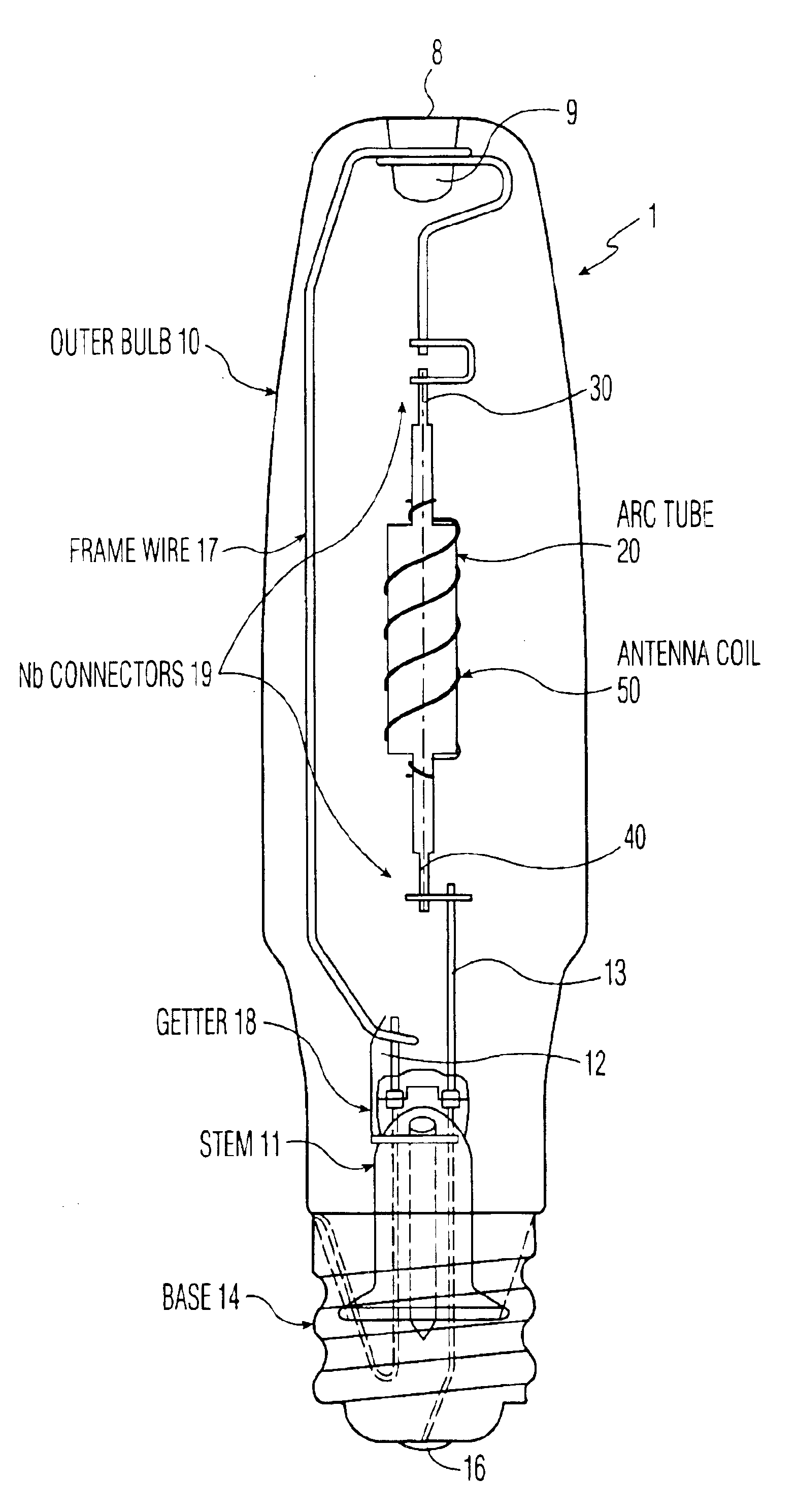
Referring to FIG. 8, a ceramic metal halide discharge lamp 1 comprises a glass outer envelope 10, a glass stem 11 having a pair of conductive frame wires 12, 13 embedded therein, a metal base 14, and a center contact 16 which is insulated from the base 14. The stem leads 12, 13 are connected to the base 14 and center contact 16, respectively, and not only support the arc tube 20 but supply current to the electrodes 30, 40 via frame wire member 17 and stem lead member 13. A getter 18 is fixed to the frame wire member 17. Niobium connectors 19 provide an electrical connection for the arc tube electrode feedthroughs 30 and 40. Beyond this the frame member 17 is provided with an end portion 9 that contacts a dimple 8 formed in the upper axial end of the glass envelope 10.

FIG. 9 shows a preferred embodiment of the arc tube 20 having a four-part feedthrough in cross-section. The central barrel 22 is formed as a ceramic tube having disc-like end walls 24, 25 with central apertures which re...


PUM

PropertyMeasurementUnit
luminous efficacyaaaaaaaaaa
correlated color temperatureaaaaaaaaaa
color rendering indexaaaaaaaaaa

Abstract

The invention relates to a high-pressure discharge lamp of the ceramic metal halide type of the Philips MasterColor series having a molybdenum coil wrapped around the discharge vessel and at least a portion of the electrode feed through means, and having power ranges of about 150 W to about 1000 W. Such lamps are provided with a discharge vessel which encloses a discharge space. The discharge vessel has a ceramic wall and is closed by a ceramic plug. An electrode which is located inside the discharge space is connected to an electric conductor by way of a leadthrough element. The leadthrough element projects through the ceramic plug with a close fit and is connected thereto in a gastight manner by way of a sealing ceramic. The leadthrough element has a first part which is formed by a cermet at the area of the gastight connection. In addition, the lamps display one or more and most preferably all of the following properties: a CCT (correlated color temperature) of about 3800 to about 4500K, a CRI (color rendering index) of about 70 to about 95, a MPCD (mean perceptible color difference) of about ±10, and a luminous efficacy up to about 85-95 lumens / watt, a lumen maintenance of >80%, color temperature shift <200K from 100 to 8000, and lifetime of about 10,000 hours to about 25,000 hours. The invention also relates to design spaces for the design and construction of high power lamps and methods for construction of such lamps using the design spaces.

Description

FIELD OF THE INVENTIONThe invention relates to a high-pressure discharge lamp which is provided with a discharge vessel that encloses a discharge space and includes a ceramic wall, the discharge space accommodating an electrode which is connected to an electric current conductor by means of a leadthrough element. The invention also relates to a high intensity discharge (HID) lamp having a discharge vessel light source, a glass stem, a pair of leads embedded in the glass stem, a glass envelope surrounding the light source, and a wire frame member with a first end fixed with respect to the stem, an axial portion extending parallel to the axis of the lamp, and a second end resiliently fitted in the closed end of the glass envelope.BACKGROUND OF THE INVENTIONHigh intensity discharge (HID) lamps are commonly used in large area lighting applications, due to their high energy efficiency and superb long life. The existing HID product range consists of mercury vapor (MV), high pressure sodiu...

Claims


Application Information

Patent Timeline
Patent Type & Authority Patents(United States)
IPC IPC(8): H01J61/00H01J61/54H01J61/06H01J61/50H01J61/12H01J61/30H01J61/82H01J61/36H01J61/02H01J61/073H01J61/16H01J61/20H01J61/56
CPCH01J61/0732H01J61/125H01J61/30H01J61/827H01J61/50H01J61/547H01J61/548H01J61/36
Inventor JACKSON, ANDREW D.GIBSON, III, RAY G.CARLETON, SARAH A.WU, SHIMINGKOWALCZYK, LOUIS N.STEERE, THOMASPALMER, JAY J.ALDERMAN, JOHN C.CONRAD, SR., JOHN E.COLLINS, KENT L.
Owner KONINK PHILIPS ELECTRONICS NV
Why Eureka
Try Eureka