Method of making an expandable medical device formed of a compacted porous polymeric material

a polymeric material and compact technology, applied in the field of medical devices, can solve the problems of vessel wall trauma, further processing, etc., and achieve the effects of improving manufacturability, improving manufacturing efficiency, and being easy to apply and remov

Inactive Publication Date: 2005-03-08
ABBOTT CARDIOVASCULAR
View PDF15 Cites 57 Cited by
  • Summary
  • Abstract
  • Description
  • Claims
  • Application Information

AI Technical Summary

Benefits of technology

The method of the invention provides for improved manufacture of a compacted porous polymeric tube for use in an expandable medical device or component. The porous polymeric tube is uniformly compacted a desired amount without buckling as it is longitudinally compacted by the heat shrink material therearound. Moreover, the heat ...

Problems solved by technology

Substantial, uncontrolled expansion of the balloon against the vessel wall can cause trauma to the vessel wall.
However, one difficulty ...

Method used


Image

  • Method of making an expandable medical device formed of a compacted porous polymeric material
  • Method of making an expandable medical device formed of a compacted porous polymeric material
  • Method of making an expandable medical device formed of a compacted porous polymeric material

Examples


Embodiment Construction

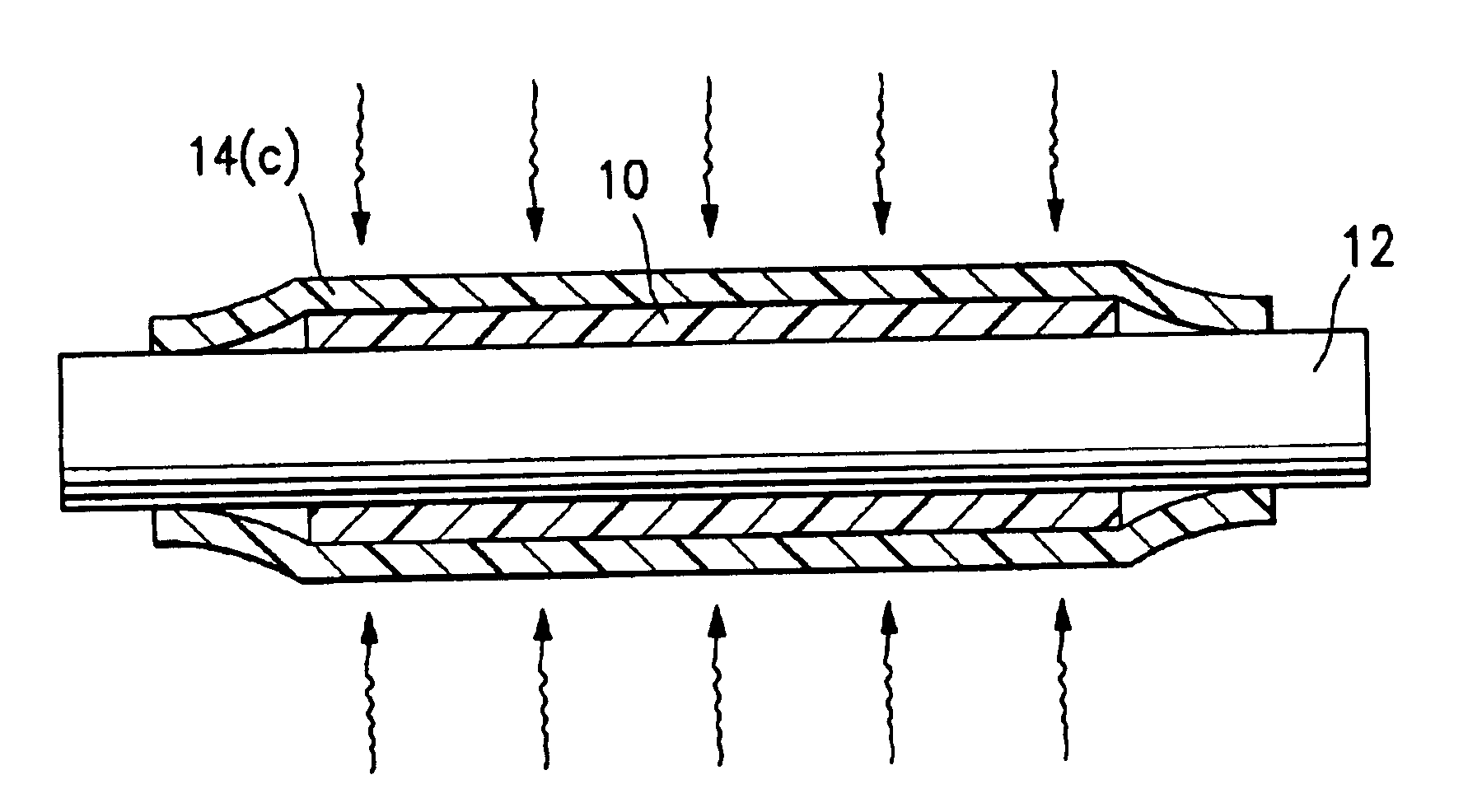
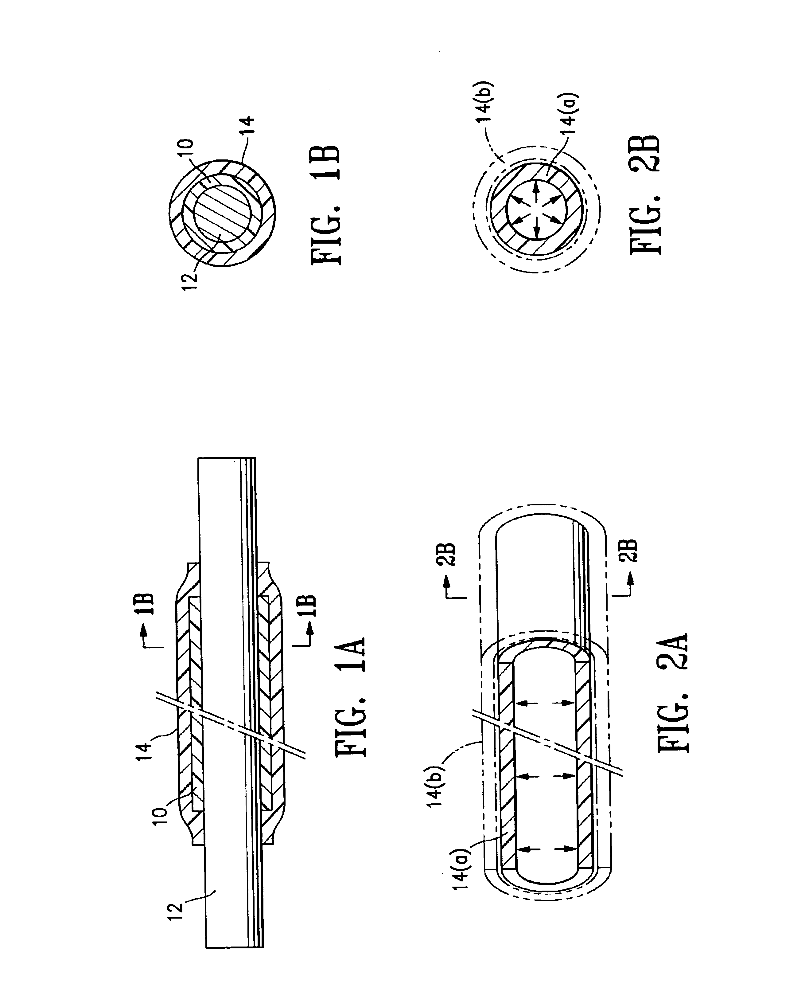
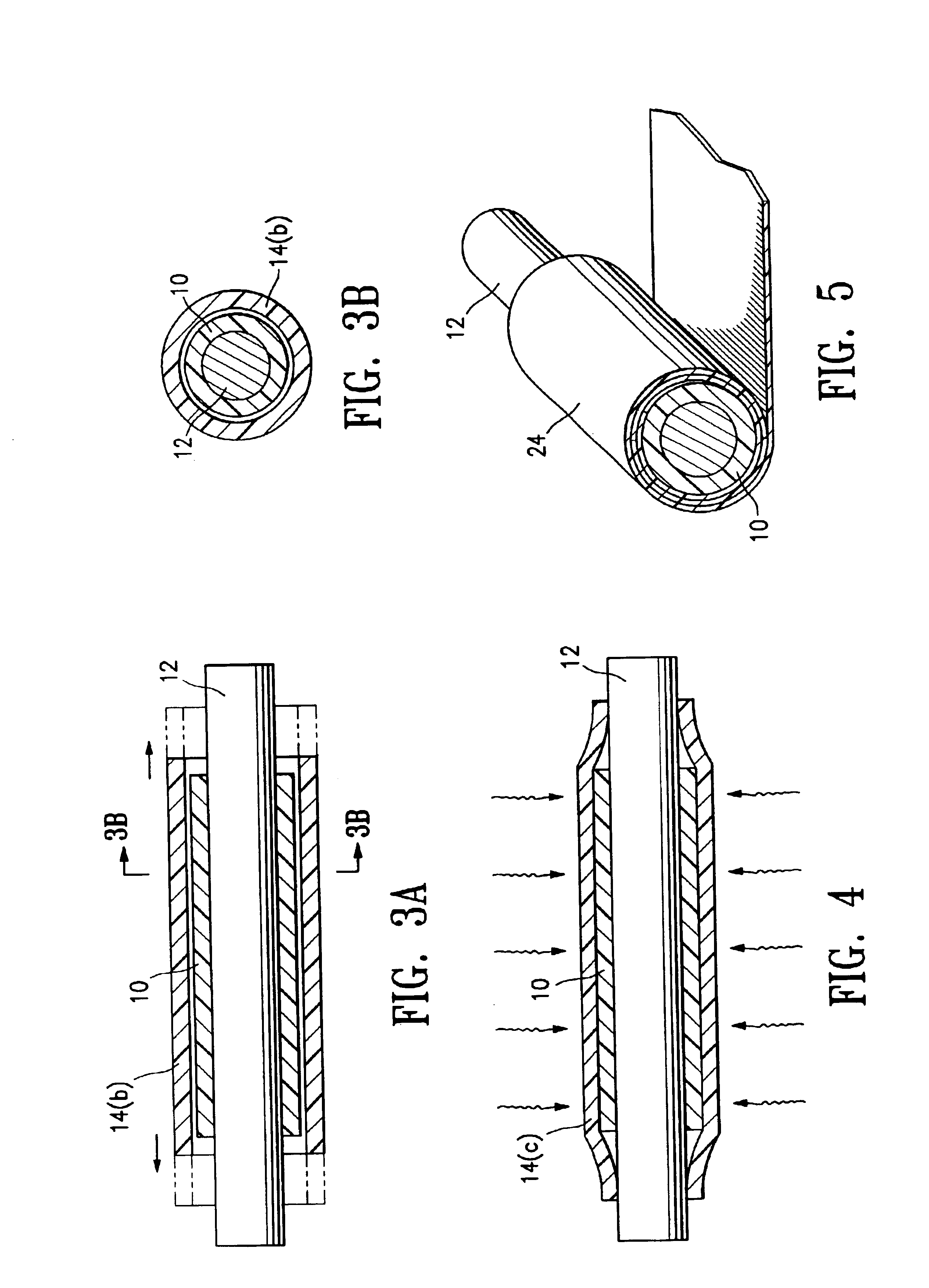
FIG. 1A illustrates a compacted tube 10 formed of porous polymeric material tube on a mandrel 12, after a tube 14 of heat shrink material has been heated to shrink the tube 14 and thereby compact the porous polymeric tube 10, in a method of making a tubular medical device of component formed of the compacted porous polymeric tube 10, embodying features of the invention. FIG. 1B is a transverse cross sectional view of the assembly of FIG. 1A, taken along line 1B—1B.

In the method of FIG. 1A, the heat shrink tube 14 is a tube of cross-linked polymeric material which has been radially expanded before being positioned on the porous polymeric tube 10, and then positioned on the porous polymeric tube 10 and longitudinally stretched down onto the porous polymeric tube 10 prior to being heat shrunk thereon to compact the porous polymeric tube 10. FIG. 2A illustrates the cross-linked polymeric tube 14(a) prior to being radially expanded, with the radially expanded cross-linked polymeric tube ...


PUM

PropertyMeasurementUnit
Temperatureaaaaaaaaaa
Fractionaaaaaaaaaa
Fractionaaaaaaaaaa

Abstract

A method of making a catheter balloon or other expandable tubular medical device or component thereof formed of a compacted porous polymeric material, in which a tube of porous polymeric material is axially compacted, preferably without increasing the outer diameter of the tube, by positioning heat shrink material on the porous polymeric tube and heating the heat shrink material to decrease the length and diameter of the heat shrink material.

Description

BACKGROUND OF THE INVENTIONThis invention generally relates to medical devices, and particularly to intracorporeal devices for therapeutic or diagnostic uses such as balloon catheters, and vascular grafts.In percutaneous transluminal coronary angioplasty (PTCA) procedures, a guiding catheter is advanced until the distal tip of the guiding catheter is seated in the ostium of a desired coronary artery. A guidewire, positioned within an inner lumen of a dilatation catheter, is first advanced out of the distal end of the guiding catheter into the patient's coronary artery until the distal end of the guidewire crosses a lesion to be dilated. Then the dilatation catheter having an inflatable balloon on the distal portion thereof is advanced into the patient's coronary anatomy, over the previously introduced guidewire, until the balloon of the dilatation catheter is properly positioned across the lesion. Once properly positioned, the dilatation balloon is inflated with fluid one or more ti...

Claims


Application Information

Patent Timeline
IPC IPC(8): B29C61/00
CPCB29C61/006B29C2049/0089B29C2049/4655B29L2031/7542B29K2023/0683B29K2027/18B29K2105/258B29C2791/001B29C2949/08
Inventor GONZALEZ, FERNANDOSRIDHARAN, SRINIVASANBLANKENSHIP, DELMA M.
Owner ABBOTT CARDIOVASCULAR
Why Eureka
Try Eureka