Magnetic barrier for plasma in chamber exhaust

a technology of magnetic barrier and plasma chamber, which is applied in the field of plasma chambers, can solve the problems of unstable main plasma body adjacent to workpiece, inability to meet the requirements of plasma process, and general corrosion of component surfaces near the plasma body within the plasma chamber, so as to achieve effective plasma blockage, minimize the magnetic field, and design

Inactive Publication Date: 2005-03-08
APPLIED MATERIALS INC
View PDF24 Cites 11 Cited by
  • Summary
  • Abstract
  • Description
  • Claims
  • Application Information

AI Technical Summary

Benefits of technology

A third aspect of the invention is an especially effective design for the magnet system comprising a cylindrical magnet and two annular pole pieces. The magnet has north and south poles at axially opposite ends, and the two pole pieces respectively abut the two ends of the magnet. Alternatively, the magnet and the pole pieces can be interchanged, so that the syst...

Problems solved by technology

One reason is that a plasma that extends a considerable distance through the exhaust channel typically is unstable, which causes the main plasma body adjacent the workpiece to be unstable, as evidenced by visible flickering of the light emitted by the plasma.
Such instability produces unacceptable non-uniformities in the plasma process.
Any component surfaces near the plasma body within a plasma chamber generally will be corroded due to bombardment by ions from the plasma.
In addition, many plasma process...

Method used


Image

  • Magnetic barrier for plasma in chamber exhaust
  • Magnetic barrier for plasma in chamber exhaust
  • Magnetic barrier for plasma in chamber exhaust

Examples


Embodiment Construction

1. Conventional Chamber Components

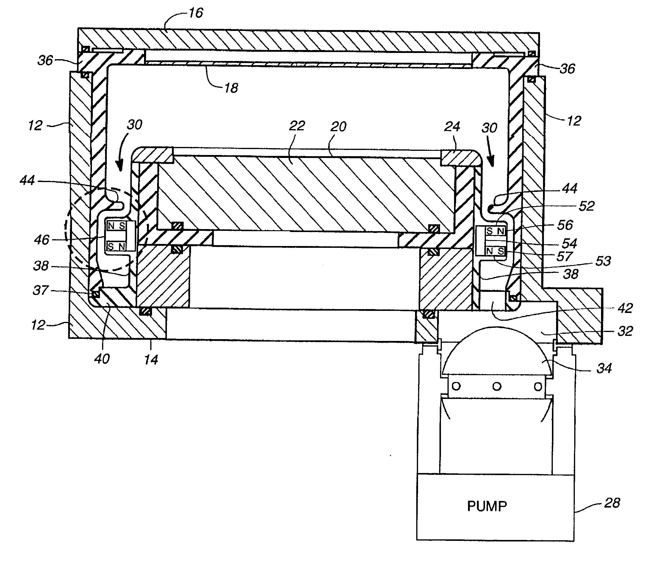
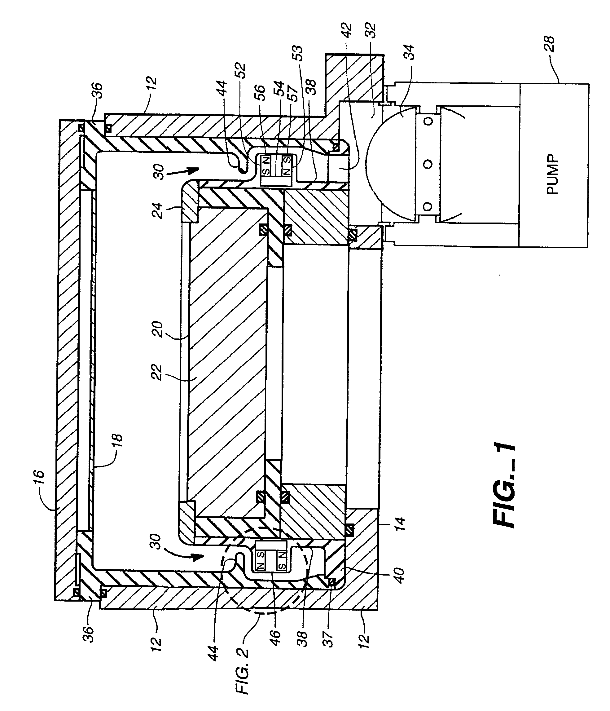
FIG. 1 shows one embodiment of the invention as applied to a plasma chamber suitable for either etching or chemical vapor deposition (CVD). The conventional components of the chamber will be described before describing the novel features for preventing the plasma from reaching the exhaust pump.

The illustrated chamber is cylindrical because it is adapted for processing a circular workpiece such as a semiconductor wafer. Alternatively, a chamber for processing a rectangular substrate conventionally would have a rectangular transverse cross section.

A cylindrical side wall 12, circular bottom wall 14, and annular top wall or lid 16 provide a vacuum tight enclosure for the chamber interior. A gas distribution plate 18, also called a diffuser or shower head, is mounted at the bottom of the lid 16. The gas distribution plate is perforated to function as a gas inlet through which process gases enter the chamber. The side wall 12 may be either dielectric or ...


PUM

PropertyMeasurementUnit
Magnetic fieldaaaaaaaaaa

Abstract

A plasma chamber apparatus and method employing a magnet system to block the plasma within the chamber interior from reaching the exhaust pump. An exhaust channel between the chamber interior and the pump includes a magnet and at least one deflector that creates turbulence in the flow of exhaust gases. The magnetic field and the turbulence produced by the deflector both increase the rate of recombination of charged particles in the gases, thereby reducing the concentration of charged particles sufficiently to quench the plasma downstream of the magnet and deflector, thereby preventing the plasma body within the chamber from reaching the exhaust pump. The plasma confinement effect of the magnetic field permits the use of a wider and/or less sinuous exhaust channel than would be required to block the plasma without the magnetic field. Therefore, the pressure drop across the exhaust channel can be reduced in comparison with prior art designs that rely entirely on the sinuousness of the exhaust channel to block the plasma. Alternatively, if the magnetic field is strong enough, the magnetic field alone can block the plasma from reaching the exhaust pump without the need for any deflector in the exhaust channel.

Description

FIELD OF THE INVENTIONThe invention relates generally to plasma chambers used in processes for manufacturing semiconductors and other electronic devices. More specifically, the invention relates to apparatus and methods for preventing plasma within the chamber from extending through the exhaust passage or exhaust channel that couples the chamber to an exhaust pump.BACKGROUND OF THE INVENTIONThe series of process steps used to fabricate semiconductors and other electronic devices commonly include various plasma processes for depositing or etching films. Such plasma processes generally are performed within a vacuum chamber whose interior is maintained at a low pressure by an exhaust pump. The pump is coupled to the chamber interior via an exhaust channel.There are several reasons that is important to prevent the plasma within the chamber from extending through the exhaust channel to the exhaust pump.One reason is that a plasma that extends a considerable distance through the exhaust c...

Claims


Application Information

Patent Timeline
IPC IPC(8): C23C16/44H01J37/32H05H1/46C23C16/50H01L21/205H01L21/3065
CPCC23C16/4412H01J37/32834H01J37/3266H01J37/32623H01J37/32
Inventor CARDUCCI, JAMES D.NOORBAKHSH, HAMIDLEE, EVANS Y.SHAN, HONGQINGSALIMIAN, SIAMAKLUSCHER, PAUL E.WELCH, MICHAEL D.
Owner APPLIED MATERIALS INC
Why Eureka
Try Eureka