
Flip-flop circuit with reduced power consumption

Inactive Publication Date: 2005-03-08
CISCO TECH INC
View PDF3 Cites 23 Cited by
  • Summary
  • Abstract
  • Description
  • Claims
  • Application Information

AI Technical Summary

Benefits of technology

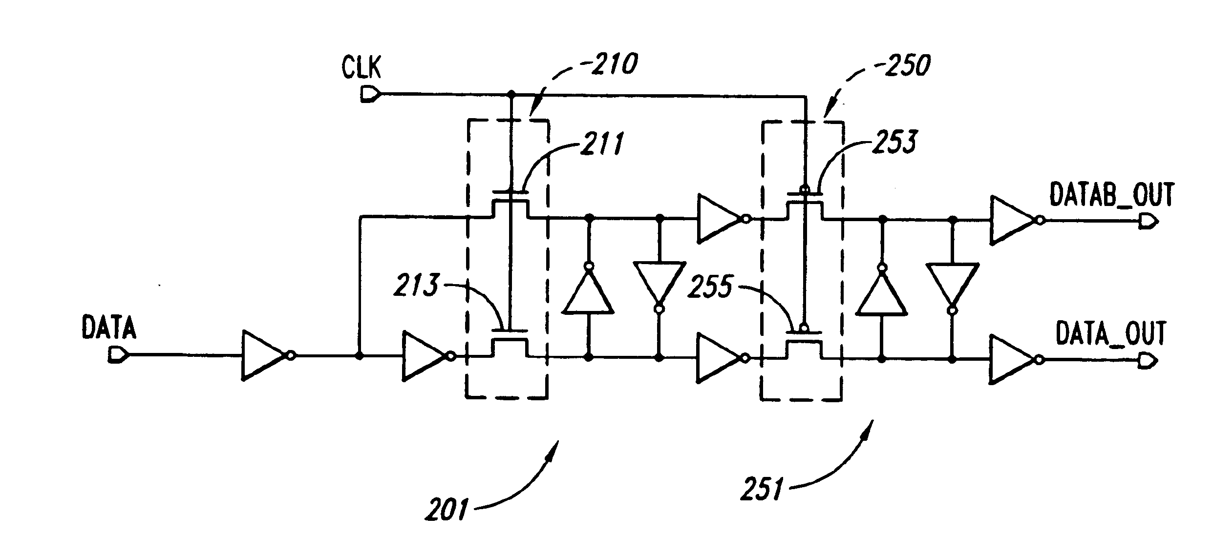
A new flip-flop design which greatly reduces clock capacitance and eliminate short-circuit current is described herein. Both these performance goals are accomplished without sacrificing the performance of the flip-flop. In the design shown and claimed herein, clock capacitance in a flip-flop is reduced by about 70% and the short circ

Problems solved by technology

All flip-flop activity consumes power.
Given that the clock runs continuously, the power consumption by flip-flops accounts for a very significant portion of the entire IC's power consumption.
As the frequency of operation and complexity of ICs is likely to increase as IC feature size shrinks, the power consumption of flip-flop circuit elements is also likely to increase significantly.
Consequently, a majority of the power consumption in a flip-flop circuit is consumed by clock switching.
Although one method for reducing the power consumption is to reduce the operating voltage, this reduction typically results in less reliable operation, as operating margins are reduced.

Method used


Image

  • Flip-flop circuit with reduced power consumption
  • Flip-flop circuit with reduced power consumption
  • Flip-flop circuit with reduced power consumption

Examples


example

Assume a microprocessor with 500,000 flip-flop circuits that operates at a frequency of 500 MHz and a power supply voltage of 1.8 V.

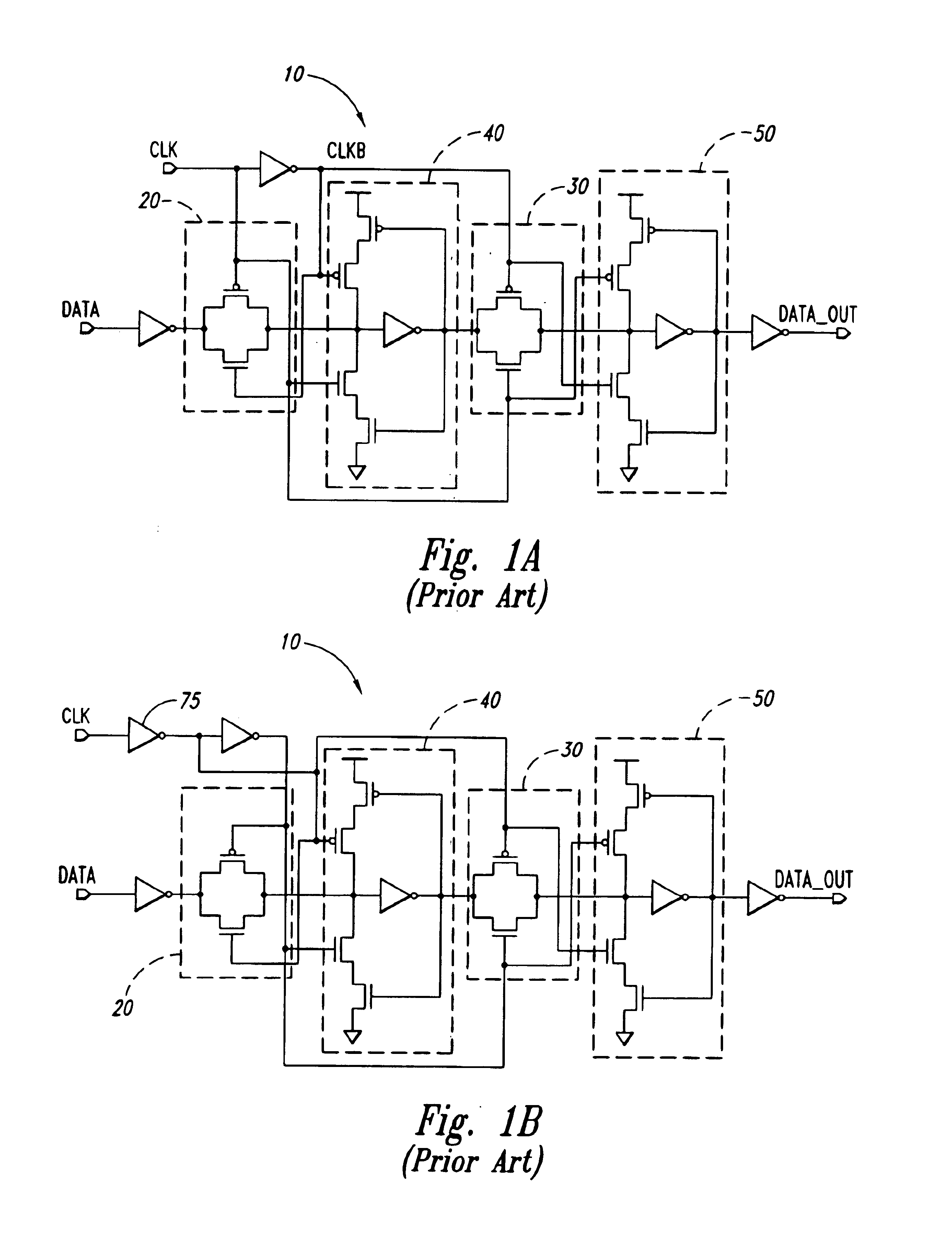
Using the flip-flop design shown in FIG. 1a, wherein the clock capacitance of each flip-flop is typically 20 ff, the power consumption will be:

Pclk=20e−15f*1.8 V2*500 MHz*500,000=16.2 watts.

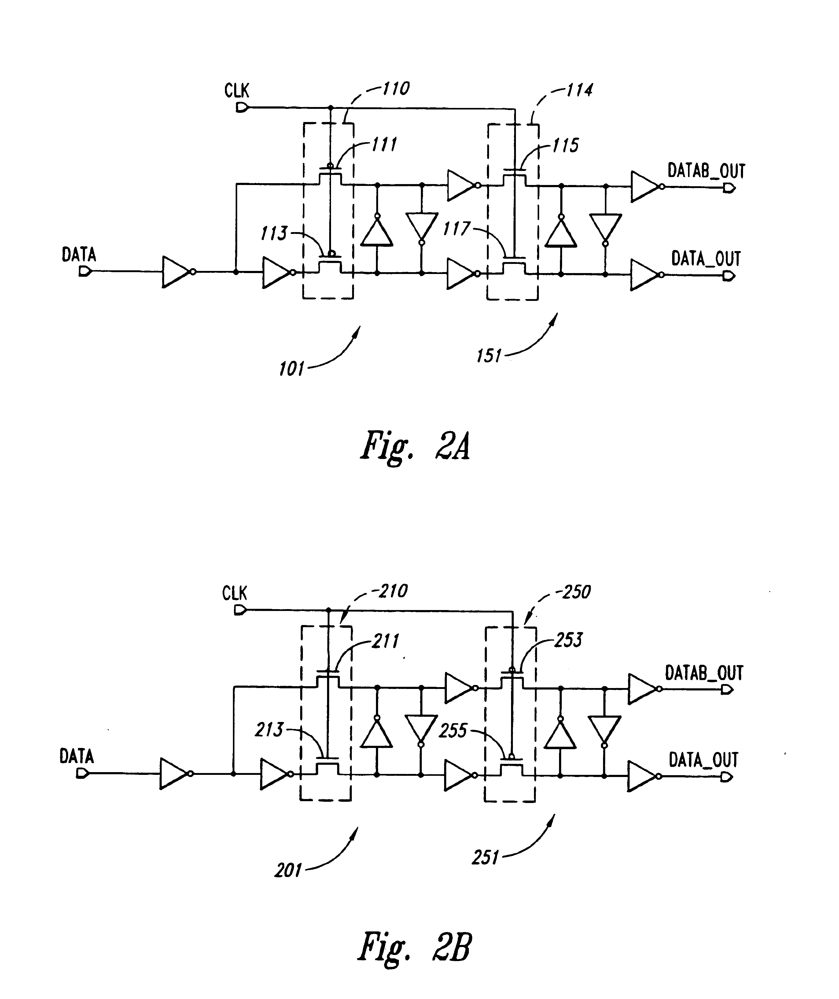
Using the design shown in FIG. 2a, wherein the clock capacitance of each flip-flop is typically 6 ff, the power consumption will be:

Pclk=6e−15f*1.8 V2*500 MHz*500,000=4.86 watts.

In this example, the power savings is almost 70%.

A careful count of the transistors needed to implement the designs shown in FIGS. 2a and 2b indicates that the present invention's flip-flop uses either the same number or very nearly the same number of transistors as the known flip-flop designs shown in FIGS. 1a and 1b. The power reduction advantages of the present invention are realized by minimizing the number of transistors that are coupled to and receive the clock signal to only the four t...


PUM


Abstract

A low power flip-flop is disclosed. The number of transistors which are coupled to the clock signal is reduced by more than half when compared with known flip-flop designs. The flip-flop comprises a pair of clocked transistors forming a pass gate and a plurality of inverters coupled thereto. By reducing the number of clock signal connections needed for reliable operation, the present invention reduces the power consumed by the flip-flop when operating at typical levels of activity by up to 70%.

Description

FIELD OF THE INVENTIONThe present invention relates broadly to logic circuit design and fabrication. It specifically relates to the design and fabrication of flip-flop circuits in Very Large Scale Integrated Circuits (VLSI).BACKGROUND OF THE INVENTIONFlip-flop circuit elements are known and widely used in VLSI integrated circuit (IC) design. Flip-flop circuit elements act as digital storage devices, receiving digital data (logic 1 or 0) at their input, storing the digital data and then providing the stored digital data as output when queried. These tasks of receiving, storing and generating output are synchronized by a clock signal.Depending upon the application, the clock signal may have a frequency of from several megahertz to several Gigahertz. In typical operations, a flip-flop receives data when the clock signal is either low or high, stores the data when the clock signal transitions from low to high or vice versa and generates its output during the clock signal's high or low s...

Claims


Application Information

Patent Timeline
IPC IPC(8): H03K3/012H03K3/037H03K3/00
CPCH03K3/0372H03K3/012
Inventor CHALASANI, PRASAD H.
Owner CISCO TECH INC
Learn More