However, with the conventional methods, the following problems have arisen for the
random pattern that is generated merely by a common random-
number generator.
Specifically, even when dots are arranged at random, the overlapping of dots and uneven dot densities, which occur because each dot has a definite size, can adversely affect the appearance of a dot pattern, and an optical malfunction, such as uneven luminance, can occur.
Further, when the dots are regularly arranged, an undesirable optical pattern, such as moire, can occur due to an interference between dots or with an external
regular pattern.
Further, according to this method, which is based on the generation of multiple pseudo random numbers, it is also difficult to remove an uneven portion from a dot pattern, even if overlapping of dots can be removed from an area having a low dot
filling rate.
However, according to a method for generating a random position as a perturbation from a lattice point, in an area having a comparatively high dot
filling rate, such as a ratio exceeding 50%, it is difficult to generate a satisfactory irregular pattern while avoiding the occurrence of moire.
Further, according to this method, which is based on the
multiplex generation of pseudo random numbers, many aggregations of dots appear even if dot overlapping is removed, and it is difficult to generate a uniform
random pattern.
However, under a condition wherein dots should not be arranged too closely together, the randomness of the dot pattern is more or less limited, even for other types of regular lattices.
Therefore, regardless of the
filling rate, this method is not satisfactory for the generation of random patterns.
In addition, relative to the optical characteristic of a dot pattern generated by the above method, another problem has arisen in that a moire pattern will occur when a
light beam is transmitted through or reflected from a dot pattern.
However, for the above mentioned reasons, it is difficult for the randomness of this method to be directly applied for uniform discrete patterns.
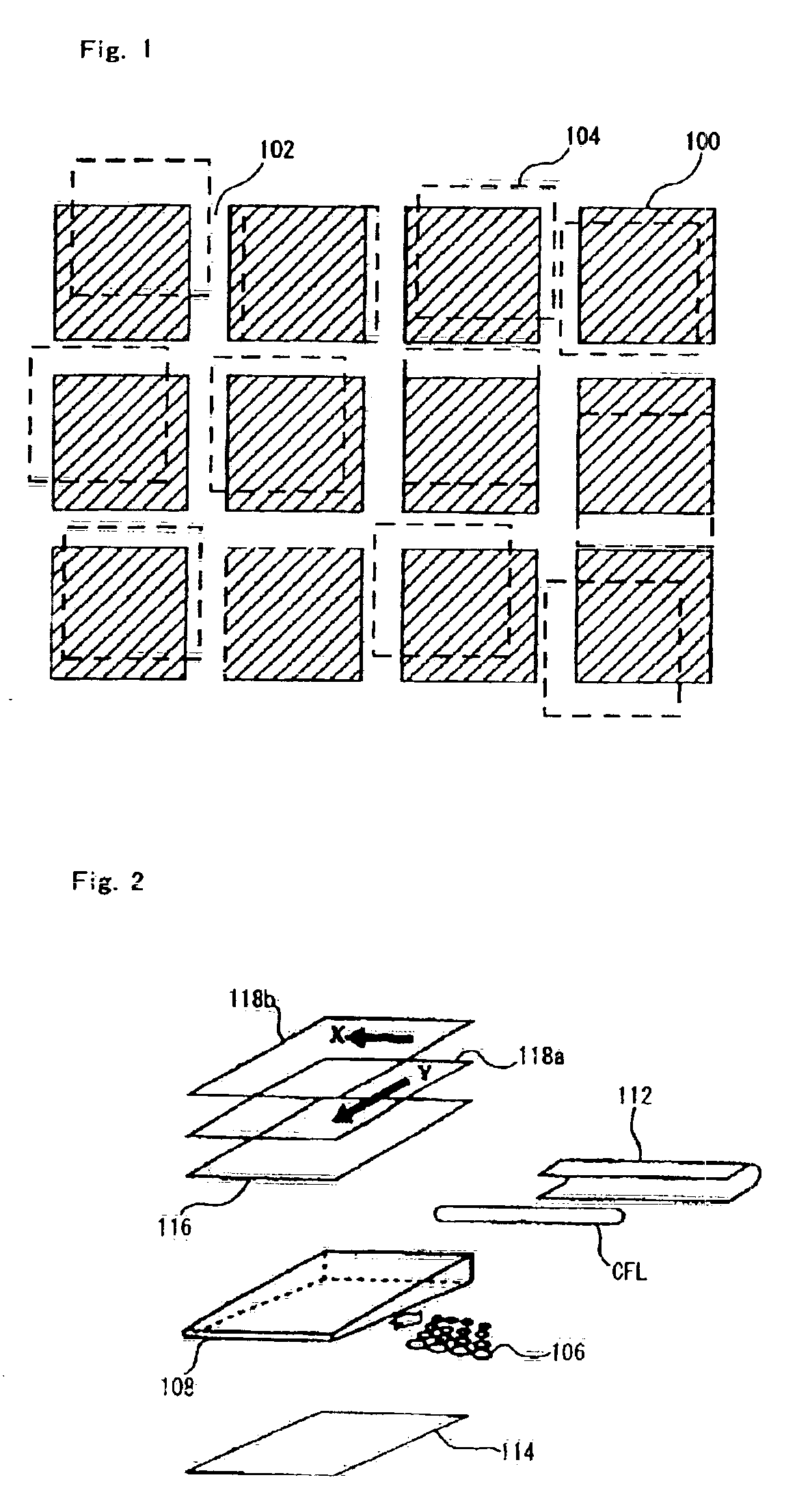
The above problems, including the generation of random dot patterns and the occurrence and removal of moire, arise not only in the printing field, wherein printing techniques for printers are affected, but also in various other fields, such as the production of display devices that include rear lighting devices (hereinafter referred to as backlights).
However, since unlike conventional display devices, i.e.,
CRTs,
liquid crystal devices do not emit light, backlight units must be provided that light all the liquid
crystal cells in these devices.
However, according to this method, it is difficult to quantitatively control the uniformity of the luminance provided by a backlight unit, and since
scattered light is wasted due to its deflection in
light scattering directions, the method is not appropriate for obtaining a high quality backlight unit that provides a
high luminance.
However, since generally an element including a small cyclic pattern, such as a color filter or a
prism sheet, is indispensable for a
liquid crystal display device, when the arrangement of a dot structure is cyclic, the dot structure and the light optically interfere with each other and generate a moire pattern.
However, with this method, a defect encountered in many cases is that at the boundaries where filling rates are changed the seams are visible.
However, excluding a case wherein the distribution is provided by a simple and easy analysis function, high level and extensive calculations are required for the generation of a lattice.
That is, the conventional method used for calculating perturbations based on a lattice point is inadequate, not only for irregularities, but also for coping with the filling rate distribution.
Furthermore, a discrete pattern, including a dot pattern having a higher quality, must be provided because the abovementioned conventional pseudo random dot patterns are inappropriate for coping with a high filling rate distribution, the uniformity of dot patterns is inappropriate, and depending on the structure of a backlight unit, the occurrence of a specific type of interference stripe can not be avoided.
Said method however requires a somewhat complicated calculation for each pixel in comparison to the
mask method which simply carries out the halftoning by comparing an input image to a given threshold value.
Further, since dot strike positions differ depending on an input image, there is a difficulty in predicting a degree of a color mixture resulting in poor
reproduction of colors.
Further, the fact that a transient region appears in a
boundary region whereto the
error diffusion method is applied and the fact that a false image called “worm” or “serpentine raster” is often observed are assumed to be unresolved problems (P.
Problems related to an
image quality however are assumed to require improvement.
In the method of distributing an error of one pixel to
peripheral limited regions, a certain degree of problem arising related to an
image quality is essentially inevitable.
The Ulichney's standards however have a defect of restrictions on a quantity of macros and said standards are therefore inappropriate as direct standards for real production of macros.
More specifically, even if conditions for a preferable power spectrum (equal to Fourier transformation of an autocorrelation function related to dot position distribution according to the Wiener-Khinchin's theorem) are presented, it is not easy to create a dot pattern or a threshold value
mask based on the dot pattern.
Further, the Ulichney's conditions are unsatisfactory in that there is no effective index directly denoting an unevenness of a dot pattern.
The initial disposition generated with pseudo-random numbers however has a defect of an apparently great unevenness and so it is impossible to binarize the initial disposition as is in high quality.
As disclosed in Japanese Patent Laid-Open Publication Heisei No. 10-275228 however, if
halftone patterns are selected appropriately based on the Ulichney's standards, a multi-
gradation pattern generated from said
halftone patterns are always somewhat not being unoptimized inappropriately.
Specifically, said methods have principle defects from the viewpoint of optimizing a dot pattern.
Further, no specific improvement of an optimization method for a start pattern is studied in Japanese Patent Laid-Open Publication Heisei No. 10-275228.
Furthermore, optimum halftoning by the one-to-one blue
mask method is not yet satisfactory and so a variety of types of improvements are being studied.
The method proposed by W. Purgathofer, R. F. Tobler and M. Greler and the method disclosed in Japanese Patent Laid-Open Publication No.2001-298617 are not satisfactory as dynamic mitigation processes.
However, it is clear that the method of Hiller, et al. has two defects.
The first defect is that it is difficult to create a dot pattern having a gradually changed
gradation by said method based on the Voronoi division.
The second defect is that use of pseudo-random numbers for generation of initial positions results in unevenness in a relaxed pattern.
Further, imposing a strong upper limit to filling factors is a great hindrance in controlling a brightness, a transitivity and a reflection factor.
Moreover, the method of employing the pseudo-
random number generation method to generate a random dot pattern may not deal with a high
filling factor and, in addition, said method has defects regarding
computer resources of a large deviation in a dot distribution and a time of work required for correction thereof.

