Vehicle-installed exhaust gas analyzing apparatus

a technology of exhaust gas analyzing and vehicle installation, which is applied in the direction of machines/engines, process and machine control, specific gravity measurement, etc., can solve the problems of unsuitable use, bulky equipment, and high cost, and achieve the effect of reducing noise and high accuracy

Inactive Publication Date: 2005-03-08
HORIBA LTD
View PDF4 Cites 23 Cited by
  • Summary
  • Abstract
  • Description
  • Claims
  • Application Information

AI Technical Summary

Benefits of technology

to provide a vehicle-installed exhaust gas analyzing apparatus including a differential pressure type flowmeter having a wide measurement range capable of securely reducing the noise in low flow rate zone wit

Problems solved by technology

In the aforementioned vehicle-installed engine exhaust gas analyzer, however, since a Fourier transform infrared analyzer (FTIR) is used for component analysis, measurement of THC is difficult, the equipment is bulky and expensive, so that it is not suited for use on board.
In the above FID method, however, an operation gas such as fuel hydrogen or supporting air is required for analysis, so that there is a problem that it is not suited for vehicle-installed application wherein compact size and measurement with simple operation are requested.
Furthermore, according to the aforementioned vehicle-installed engine exhaust gas analyzing apparatus, though it is possible to continuously measure concentration and mass of a specific component contained in exhaust gas, it is necessary to mount a trace gas source in the vehicle and inject trace gas into the exhaust pipe while measuring the trace gas from an appropriate position for measuring exhaust gas flow rate by means of the exhaust gas flow rate measuring device, so that configuration for measuring exhaust gas flow rate is complicated.
Furthermore, when the exhaust gas flow rate measuring

Method used


Image

  • Vehicle-installed exhaust gas analyzing apparatus
  • Vehicle-installed exhaust gas analyzing apparatus
  • Vehicle-installed exhaust gas analyzing apparatus

Examples


Embodiment Construction

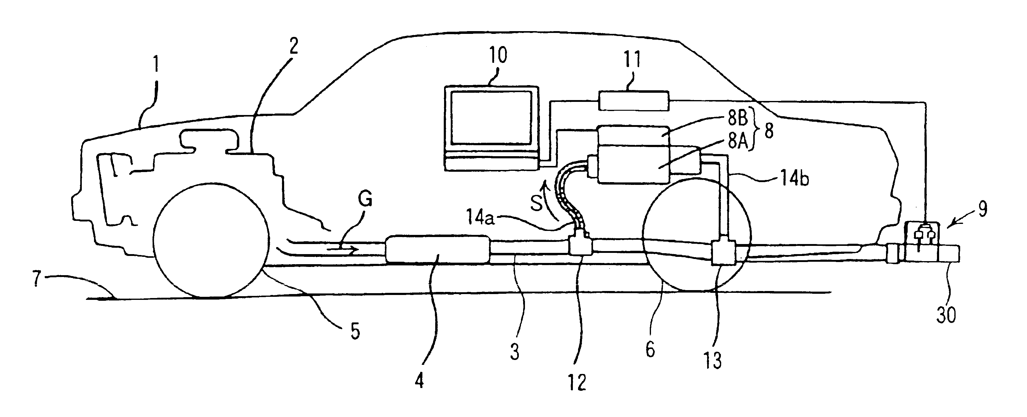
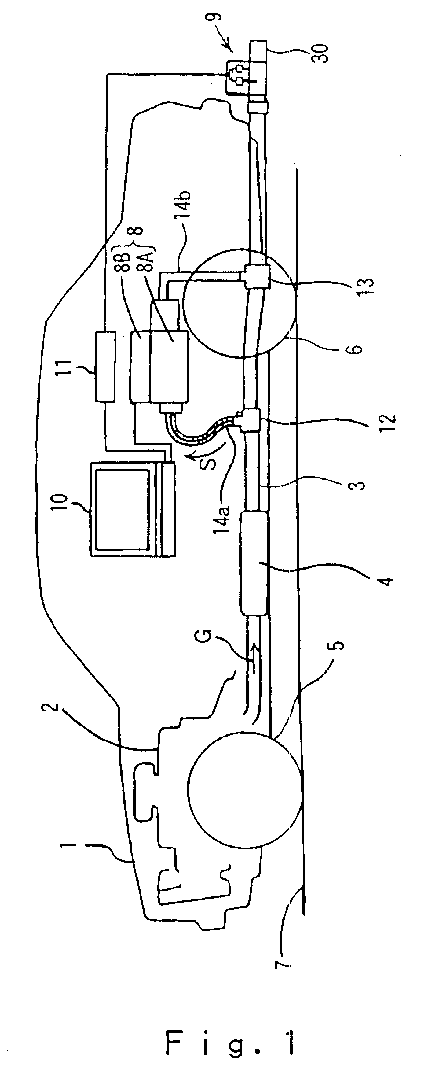
In the following, the detail of the present invention will be explained with reference to the drawings. FIGS. 1 to 5 show one example of a vehicle-installed exhaust gas analyzing apparatus according to the present invention. First FIG. 1 shows an embodiment in which said vehicle-installed exhaust gas analyzing apparatus is installed in an automobile, and in this view, the reference numeral 1 denotes an automobile serving as a vehicle to be subjected to measurement. The reference numeral 2 denotes an engine of the automobile 1, the numeral 3 denotes an exhaust pipe connecting with the engine 2 and through which an exhaust gas G flows, the numeral 4 denotes a catalyst device provided in the exhaust pipe 3. The reference numerals 5, 6 respectively denote a front wheel and a rear wheel of the automobile 1, and the numeral 7 denotes a road surface.

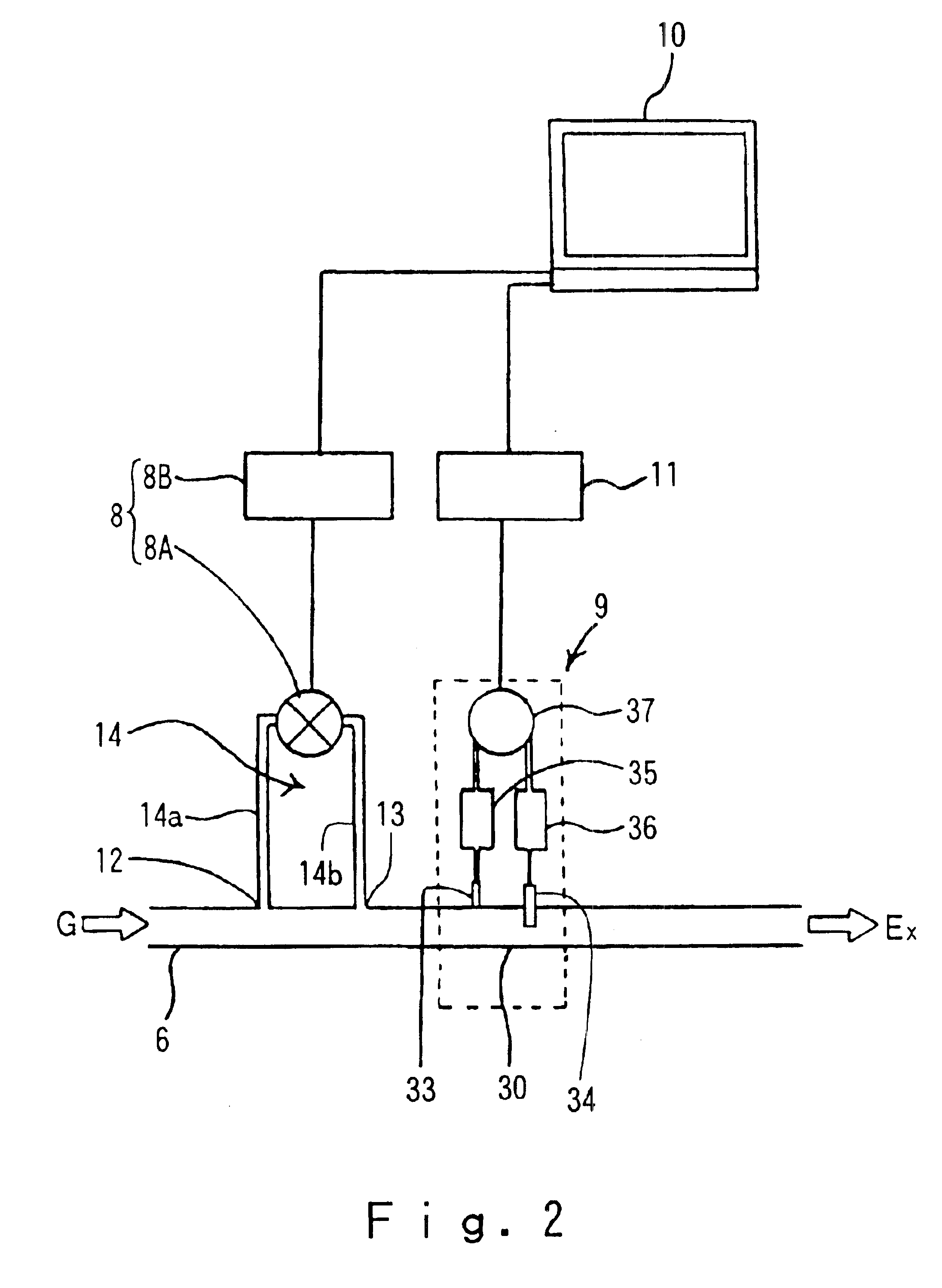
The exhaust pipe 3 is provided with an NDIR type gas analyzer 8 and an exhaust gas flowmeter 9 as shown in FIG. 2. That is, said NDIR type gas...


PUM


Abstract

A vehicle-installed exhaust gas analyzing apparatus includes a nondispersive infrared (NDIR) type gas analyzer for continuously measuring concentration of hydrocarbon (HC) in an exhaust gas flowing through an exhaust pipe which is connected to an engine, an exhaust gas flowmeter for continuously measuring flow rate of the exhaust gas flowing through the exhaust pipe, and an operation processing device for processing outputs from the NDIR type gas analyzer and the exhaust gas flowmeter to continuously calculate mass of total hydrocarbon (THC) contained in the exhaust gas. The components are configured so at to be installable in vehicle. THC concentration is obtained by multiplying a measurement result obtained by the NDIR type analyzer by a predetermined conversion factor.

Description

BACKGROUND OF THE INVENTION1. Field of the InventionThe present invention relates to a vehicle-installed exhaust gas analyzing apparatus capable of real time measuring concentration of hydrocarbons (HC) contained in exhaust gas emitted from an engine of a vehicle such as automobile running on the road. The present invention also relates to a vehicle-installed exhaust gas analyzing apparatus for continuously measuring mass of total hydrocarbon (THC) (mass emission) contained in exhaust gas from an engine of a vehicle such as automobile. Furthermore, the present invention relates to a vehicle-installed exhaust gas analyzing apparatus equipped with a differential pressure type flowmeter such as Pitot tube type flowmeter.2. Background ArtIn recent years, increasing concerns about influence of exhaust gas emitted from engines etc. (hereinafter, simply referred to as exhaust gas) on the environment have raised the trend that the actual condition should be grasped in a condition similar to...

Claims


Application Information

Patent Timeline
IPC IPC(8): F01N7/00G01M15/04G01M15/10G01N33/00F01N13/00
CPCF01N13/008G01N33/0062G01M15/104G01N21/3504
Inventor NAKAMURA, HIROSHI
Owner HORIBA LTD
Why Eureka
Try Eureka