Disposable net assemblies for apparatus for collecting floating debris

a technology of floating debris and nets, which is applied in the direction of sedimentation settling tanks, separation processes, filtration separation, etc., can solve the problems of reducing the overall effective area of the filter, excessive extreme forces, and floatable material filling of the net, etc., to achieve convenient replacement, strong and reliable, and easy construction

Inactive Publication Date: 2005-03-15
FRESH CREEK TECH
View PDF13 Cites 29 Cited by
  • Summary
  • Abstract
  • Description
  • Claims
  • Application Information

AI Technical Summary

Benefits of technology

A primary objective of the present invention is to provide a stronger and more reliable mesh net for the traps of systems for collecting floatable debris than have be...

Problems solved by technology

Trash and debris floating on the surfaces of waterways or along shorelines and beaches is a highly visible form of water pollution, which is receiving attention for its adverse, polluting effect and for its unaesthetic appearance on the surfaces of lakes and other water bodies.
There are many outfalls where extreme forces exist that are too high for standard and commonly available materials or for materials made by normal fabrication practices to last.
Furthermore, the operation...

Method used


Image

  • Disposable net assemblies for apparatus for collecting floating debris
  • Disposable net assemblies for apparatus for collecting floating debris
  • Disposable net assemblies for apparatus for collecting floating debris

Examples


Embodiment Construction

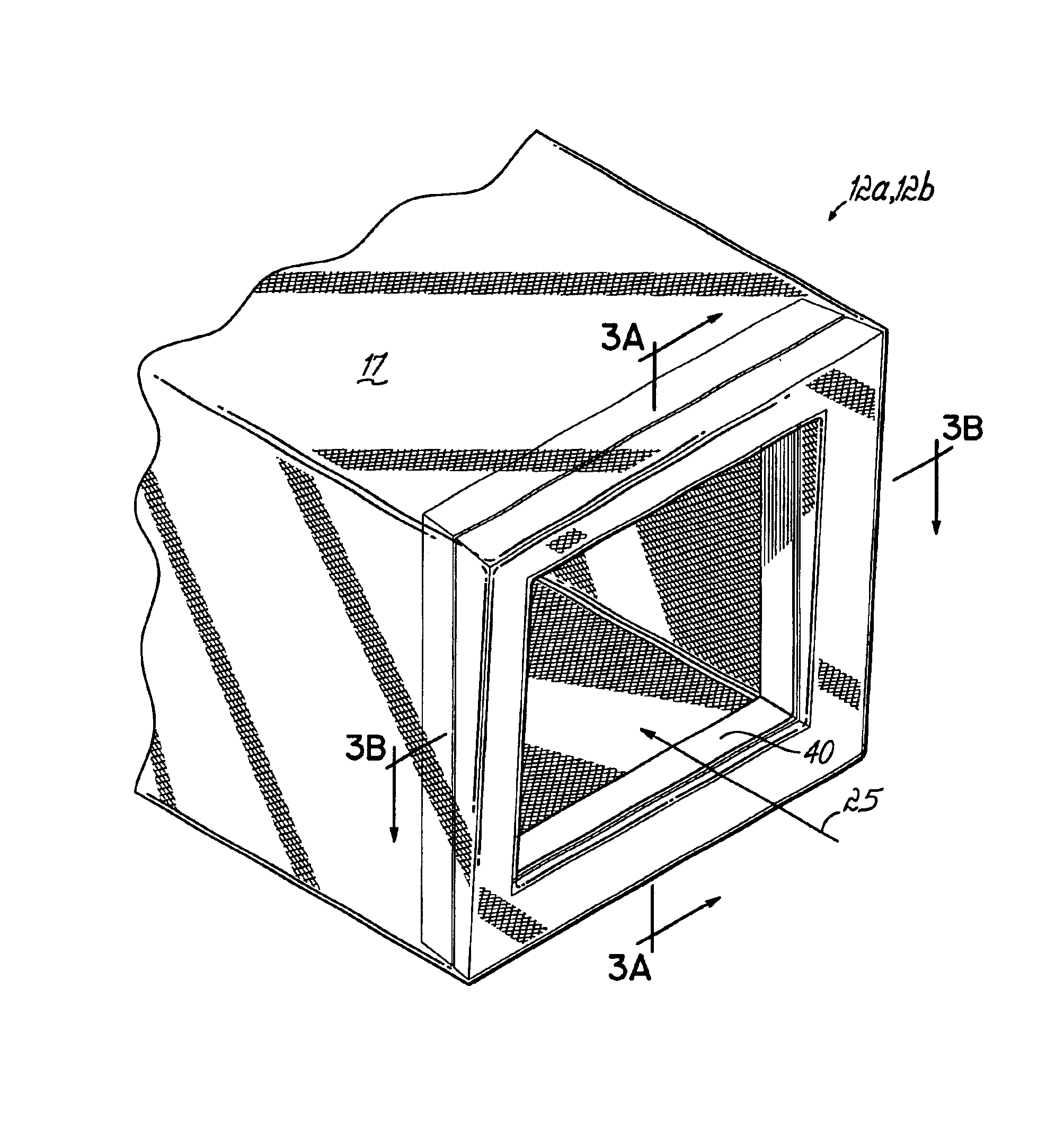
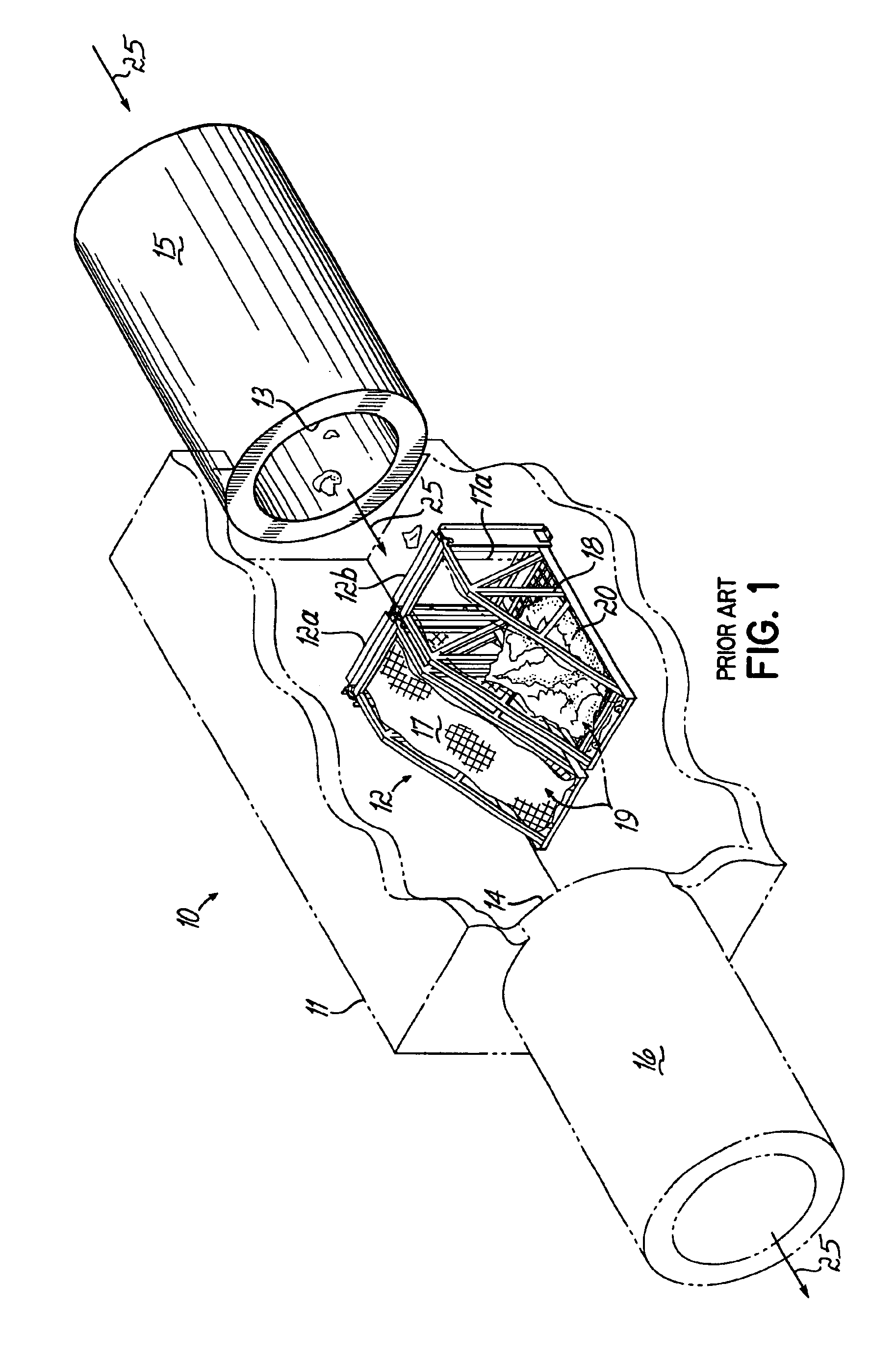
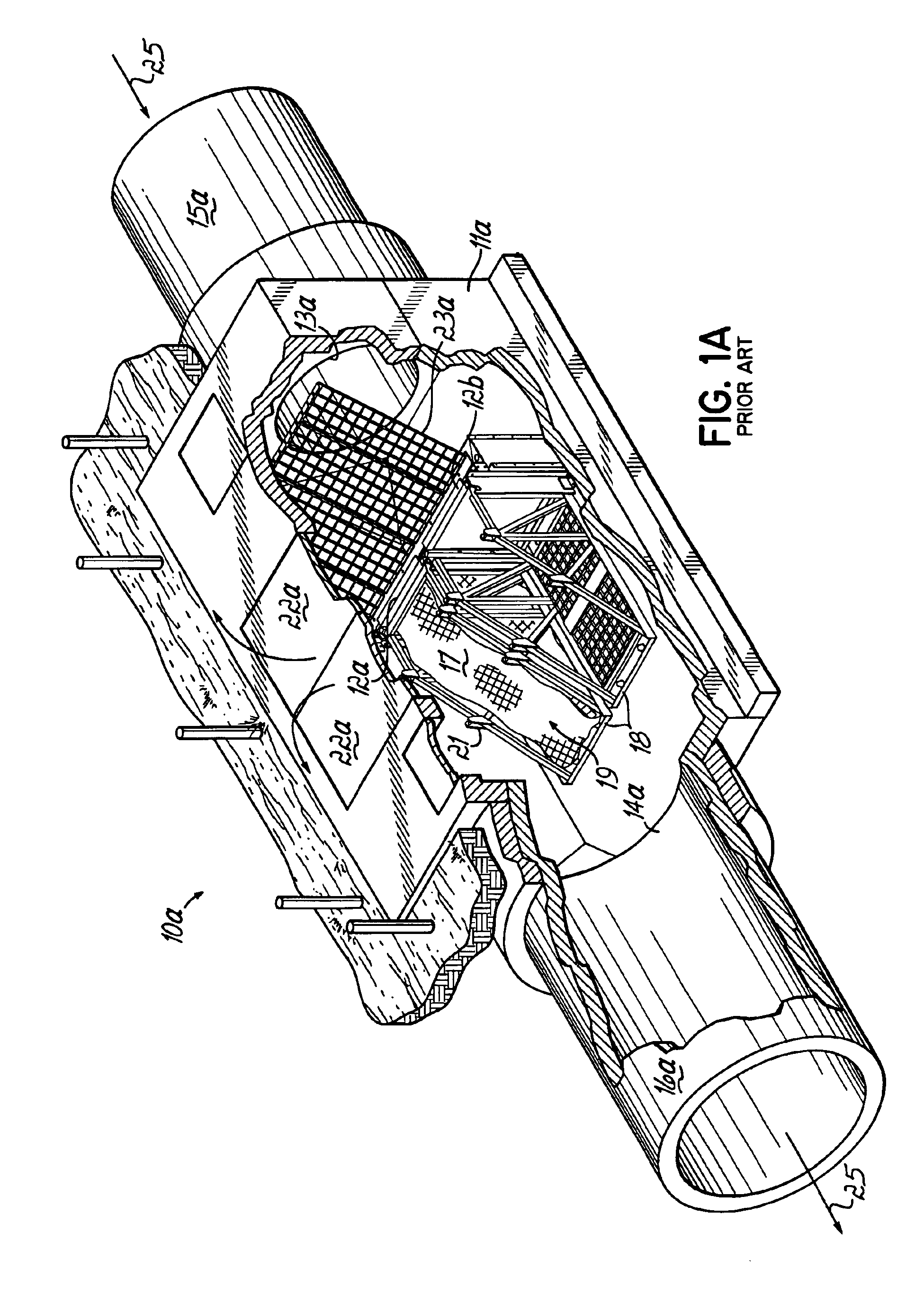
FIG. 1 illustrates the basic components of one system 10 of the prior art described in the background of the invention above. The system 10 includes one or more traps 12, illustrated as two in number, separately designated as traps 12a and 12b. The traps 12a,12b are located within a flow constraining housing or enclosure 11 between inlet 13 and outlet 14 thereof. The inlet 13 and the outlet 14 are each respectively connected in a known manner to conduits 15 and 16, which may be storm drain or combined sewer conduits or other structures or the terrain of the site. The traps 12a,12b each include a netting assembly 19 formed of a bag-shaped mesh net 17 that is attached to a lifting basket 18. Each of the netting assemblies 19 captures and holds floatable velocity borne debris 20 entering enclosure 11 through inlet 13. The arrows 25 indicate the direction of water flow.

Perforations or openings in nets 17 may vary in size depending on the intended use, with sizes generally in the range o...


PUM

PropertyMeasurementUnit
Forceaaaaaaaaaa
Strengthaaaaaaaaaa
Stress optical coefficientaaaaaaaaaa

Abstract

A disposable net assembly is provided for a trap for collecting floatable debris in a waterway or combined sewer system. The net assembly includes a knitted bag-shaped mesh net having a frame surrounding the mouth of the net with the net secured around its rim to the frame. The net may be formed of an inner layer and an outer layer of mesh with the openings of the inner layer being substantially larger than the openings of the outer layer. The frame may be formed of a plastic molded material having side members tapered in the vertical direction to facilitate the changing of the netting assemblies and tapered in the downstream direction to lock into place under the force of the flow. Several embodiments of the frame members have projections thereon which cooperate with a clamping element to hold the net to the frame. Some embodiments of the members have parts that lock together with a post and hole construction while others employ a tension band to clamp the net to the projections on the frame. The net is preferably secured around its rim to the frame, with the mouth of the net extending around the outside and upstream side of the frame and over the surface having the projections. The net is preferably formed of a high strength and high stretch yarn, with rolled sewn seams and having reinforcing on the seams and on high stress areas of the net.

Description

The present invention generally relates to the collection and removal of trash or floating debris from waterways and, more particularly, to systems designed for use in combined sewer systems or storm drain conduits to trap water borne trash for removal.BACKGROUND OF THE INVENTIONTrash and debris floating on the surfaces of waterways or along shorelines and beaches is a highly visible form of water pollution, which is receiving attention for its adverse, polluting effect and for its unaesthetic appearance on the surfaces of lakes and other water bodies. One type of system for the collecting and removing of floating debris has consisted of arrays of disposable mesh nets installed in receiving bodies of water in the flow path of a sewer outlet, particularly in applications referred to as “Combined Sewer Overflows” or “CSOs”. Such systems are described in Vol. 2, No. 3, of Fresh Creek Technologies, Inc. “Shorelines” newsletter. Systems of this type are effective in collecting floatables...

Claims


Application Information

Patent Timeline
IPC IPC(8): B01D21/00B01D29/27B01D29/13E02B8/00E02B8/02
CPCB01D21/0012B01D21/02B01D21/2405B01D21/2433B01D21/2444B01D29/27E03F5/14B01D2221/12Y10T428/249921
Inventor TURNER, JR., RICHARD R.KIRCHER, ROBERTMORAN, DENNIS R.DUGAN, JAMES P.
Owner FRESH CREEK TECH
Why Eureka
Try Eureka