Drive head and ECM method and tool for making same

a technology of drive head and ecm, which is applied in the direction of manufacturing tools, electrical-based machining electrodes, machining working media supply/regeneration, etc., can solve the problems of increasing the difficulty of fabricating drive head for bolts, affecting the ability to provide double hexagonal configuration, and reducing the strength or fatigue life of materials, so as to facilitate the supply of sufficient torque.

Inactive Publication Date: 2005-03-15
LEHR PRECISION +1
View PDF45 Cites 19 Cited by
  • Summary
  • Abstract
  • Description
  • Claims
  • Application Information

AI Technical Summary

Benefits of technology

The drive portion of the drive head of the present invention can be provided with sharp and well-defined edges at each corner to allow the drive tool (e.g., wrench) to grip the drive portion and easily supply sufficient torque to twist or rotate the drive head. This can be achieved by using the electrochemical machining method and tool of the present invention, even when the drive portion of the drive head has a double hexagonal configuration (i.e., twelve corners), as wel...

Problems solved by technology

The difficulty in fabricating drive heads for bolts becomes greater as the number of points or corners increases in number.
This makes it more difficult to provide a double hexagonal configuration in drive head having points or corners that are sufficiently well-defined and sharp so that the wrenching tool can engage the drive head without stripping the points or corners over time.
The difficulty in fabricating drive heads for bolts can also be affected by the ductility (malleability) of the metal, especially at the forging temperature used to make the bolt.
However, for bolts made from metals that need to be forged in a very narrow temperature range, such as powder metal alloys (e.g., nickel alloys containing significant levels of nickel (e.g., at least about 40%) and other metals such as cobalt and chromium), conventional deforming techniques typically used to make bolts have no...

Method used


Image

  • Drive head and ECM method and tool for making same
  • Drive head and ECM method and tool for making same
  • Drive head and ECM method and tool for making same

Examples


Embodiment Construction

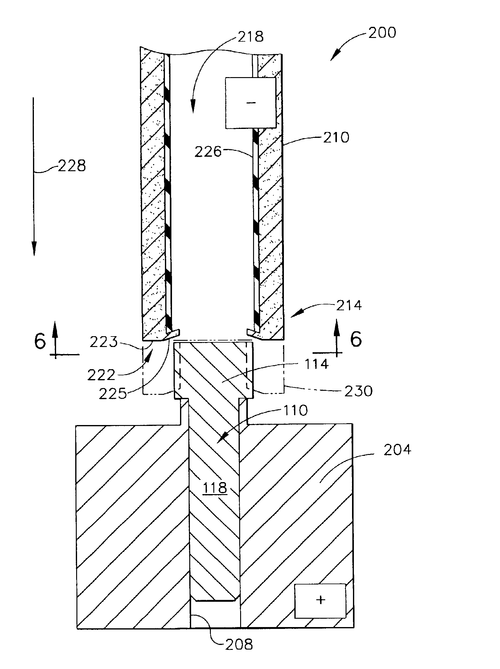
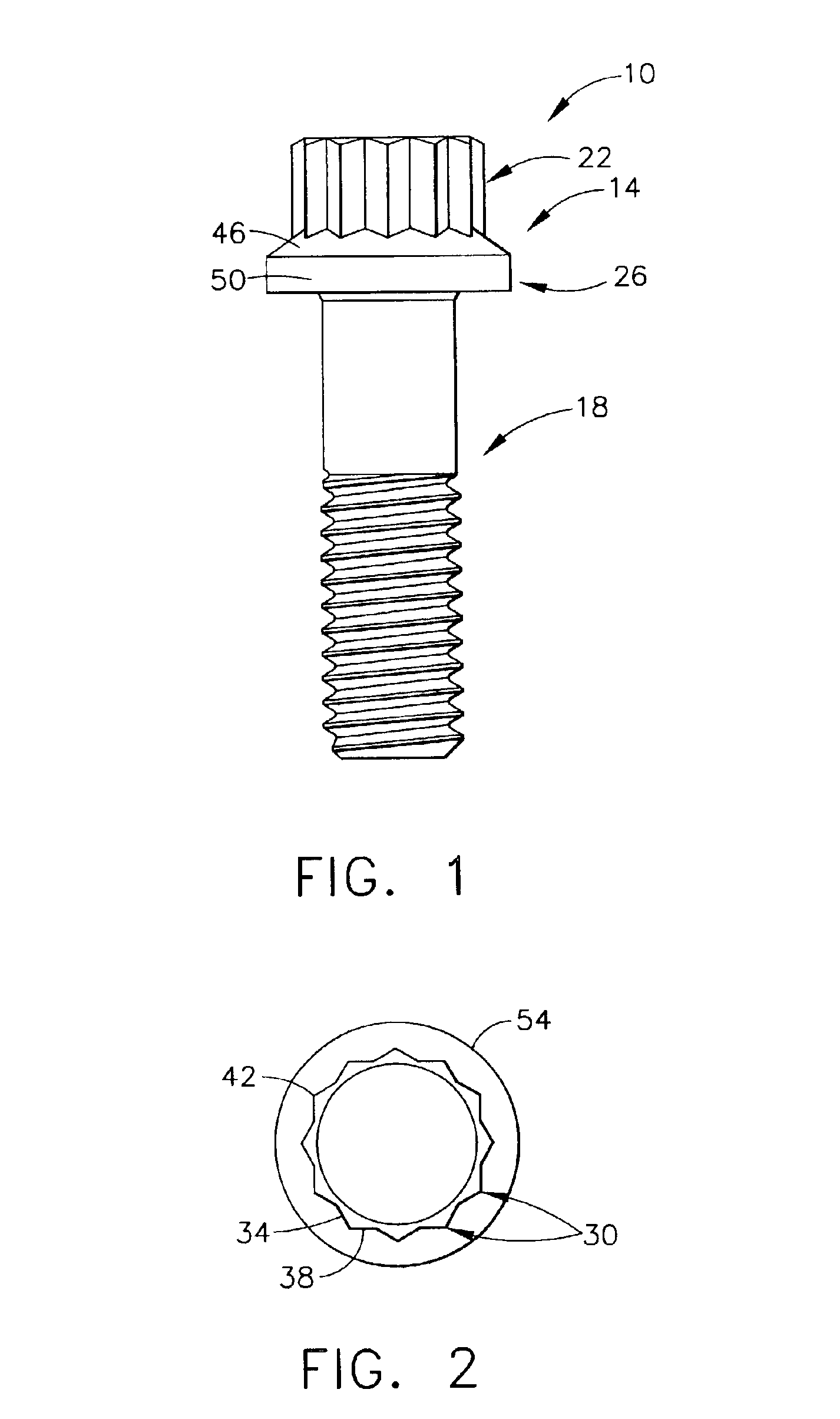
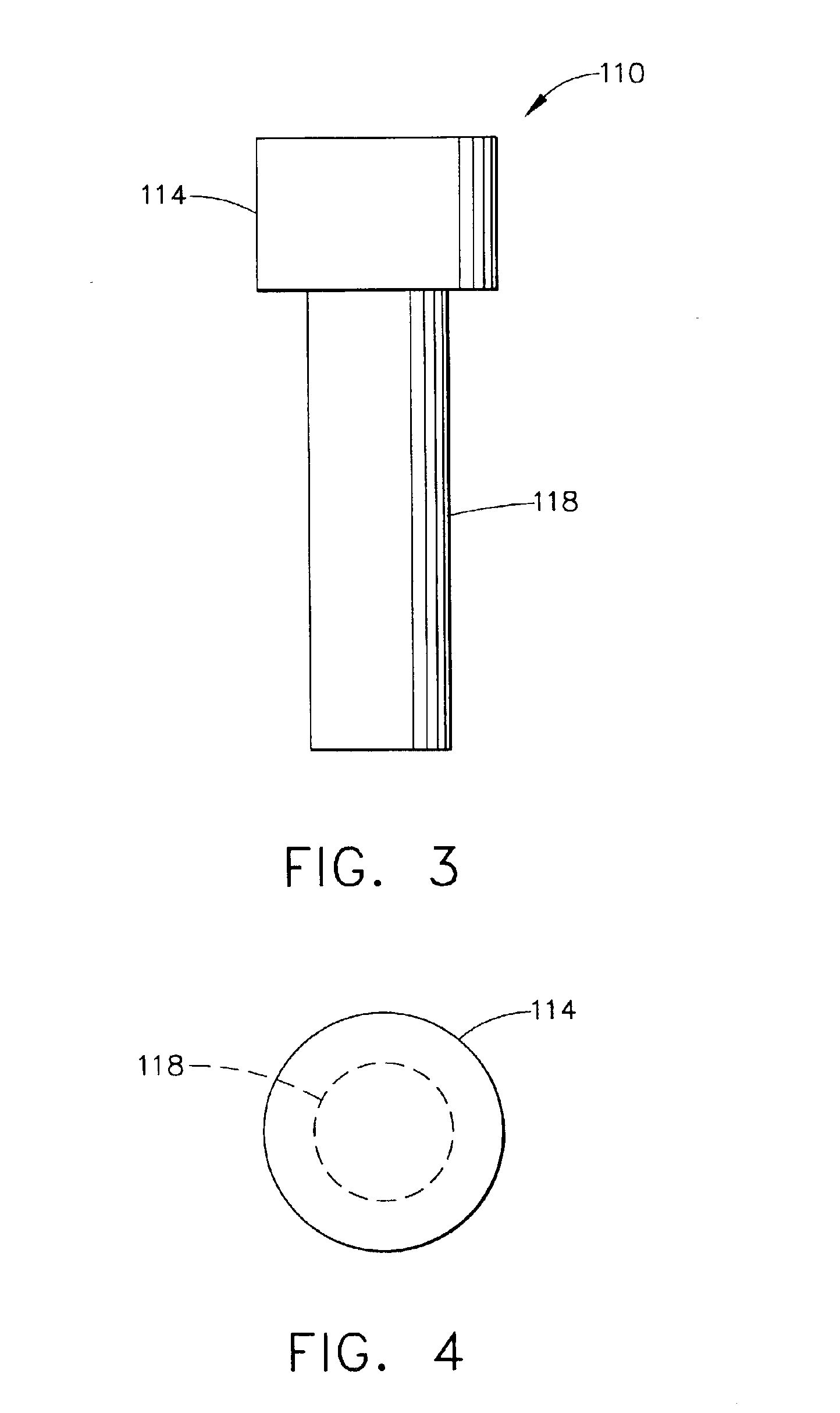
As used herein, the term “driveable article” refers to those articles that have a drive head and are generally twisted or rotated about a longitudinal axis by a tool (e.g., wrench) or other drive component. Driveable articles include fasteners such as bolts, or nuts, couplings such as curvic couplings, splines, gears, etc.

As used herein, the term “less malleable metal” refers to those metals that are difficult or impossible to shape or form by conventional bolt forging techniques. These harder, less malleable metals and metal alloys include powder metal nickel alloys comprising at least about 40% nickel (e.g., from about 40 to about 75%), more typically at least about 45% nickel (e.g., from about 45 to about 60%). These powder metal nickel alloys can also comprise at least about 5% cobalt (e.g., from about 5 to about 21%), more typically at least about 12% cobalt (e.g., from about 12 to about 14%) and at least about 10% chromium (e.g., from about 10 to about 22%), more typically at ...


PUM

PropertyMeasurementUnit
Fractionaaaaaaaaaa
Fractionaaaaaaaaaa
Fractionaaaaaaaaaa

Abstract

A drive head for a bolt, fastener, coupling, nut or other driveable head made from a less malleable metal such as a powder metal nickel alloy. The drive head has an upper drive portion having at least six convex corners spaced around the outer periphery thereof, each corner terminating in an edge. The drive head also has a lower flange portion adjacent to the drive portion and having an edge extending radially outwardly to at least the edge of each corner. The drive portion and the flange portion of the drive head is formed by subjecting a blank having a generally circular head to electrochemical machining (ECM). A tool is also provided for the ECM method to form the drive portion and flange portion of the drive head.

Description

BACKGROUND OF THE INVENTIONThe present invention relates generally to a drive head, such as for a bolt, coupling, nut or the like, particularly those made from metals that are less malleable at forging temperatures and thus require special methods in making to prevent cracking. The present invention further relates to an electrochemical machining method, as well as a tool, useful in making such a drive head.Fasteners such as bolts or nuts are typically provided with a drive head that can be gripped by the tool, e.g., wrench, so that sufficient torque can be generated to twist or rotate the fastener. The external surface of the drive head can have a number of different configurations. Some typical configurations include square heads (i.e., having four points or corners) and hexagonal heads (i.e., having six points or corners). See, for example, U.S. Pat. No. 3,492,908 (Thurston), issued Feb. 3, 1970, which shows a bolt having a hexagonal head. Other configurations include those havin...

Claims


Application Information

Patent Timeline
IPC IPC(8): B23H9/00B23H3/04B23H3/00
CPCB23H3/00B23H9/00B23H3/04
Inventor ANDERSON, WILLIAM C.STAMM, EDWARD I.BUDINGER, VICKY S.LIEVESTRO, TERRY L.
Owner LEHR PRECISION
Why Eureka
Try Eureka