Method for manufacturing PDLC-based electro-optic modulator using spin coating

a technology of electro-optic modulators and spin coatings, which is applied in the direction of coatings, instruments, pre-treated surfaces, etc., can solve the problems of low yield of final modulators, lack of surface flatness and smoothness, and edge/corner defects

Inactive Publication Date: 2005-03-15
PHOTON DYNAMICS
View PDF7 Cites 38 Cited by
  • Summary
  • Abstract
  • Description
  • Claims
  • Application Information

AI Technical Summary

Benefits of technology

According to the invention, electro-optic structures are constructed by spin coating water-based emulsions or solvent-based sensor materials, preferably a solvent-based polymer dispersed liquid crystal (PDLC), onto a substrate under conditions of controlled solvent evaporation. In a particular process, the uniformity of the PDLC coating is achieved by 1) spin coating in a semi-sealed chamber, 2) “converting” a square substrate into round substrate by using a fixture; 3) providing a controllable distance between the substrate and a spin coater top cover; and 4) providing a controllable solvent evaporation rate.

Problems solved by technology

Due to various complications, the result was relatively low yield of the final modulator.
Problems included lack of surface flatness and smoothness, and edge / corner defects.
The top layer Mylar peeling process further generated thickness variation, surface roughness, edge / corner defects, and electro-optical non-uniformity.
However, this transfer coating process has been found to have limitations because the process cannot eliminate thickness non-uniformity of NCAP material, and because, between NCAP and a glass substrate, the process requires UV-curable adhesive.
It has been found that this adhesive damages NCAP film during the process.
Therefore, transfer coating is not suited to all desired assembly processes.

Method used


Image

  • Method for manufacturing PDLC-based electro-optic modulator using spin coating
  • Method for manufacturing PDLC-based electro-optic modulator using spin coating
  • Method for manufacturing PDLC-based electro-optic modulator using spin coating

Examples


Embodiment Construction

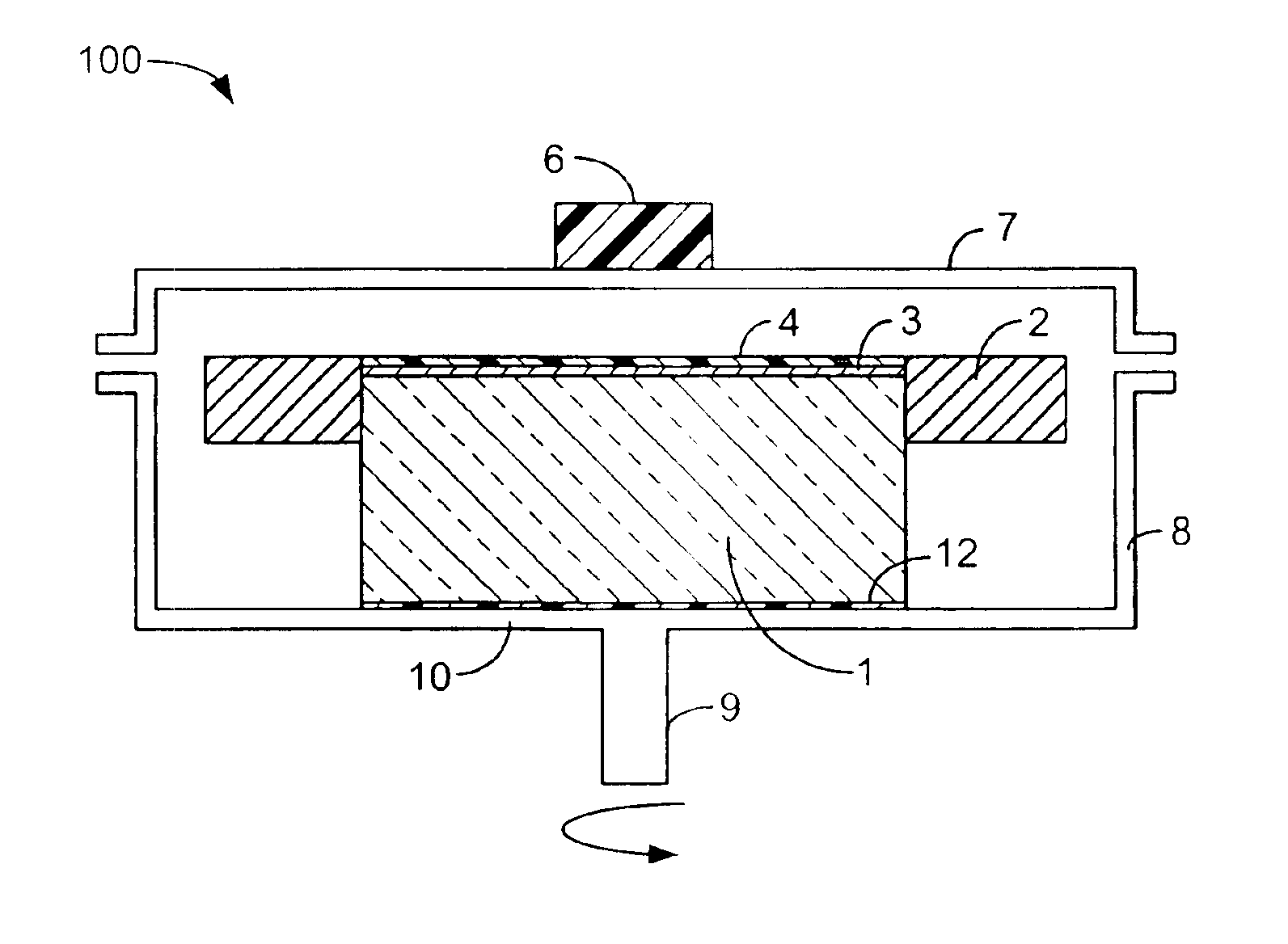
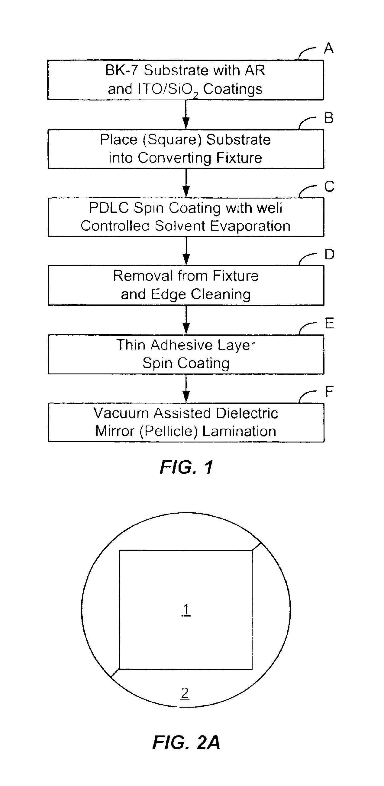
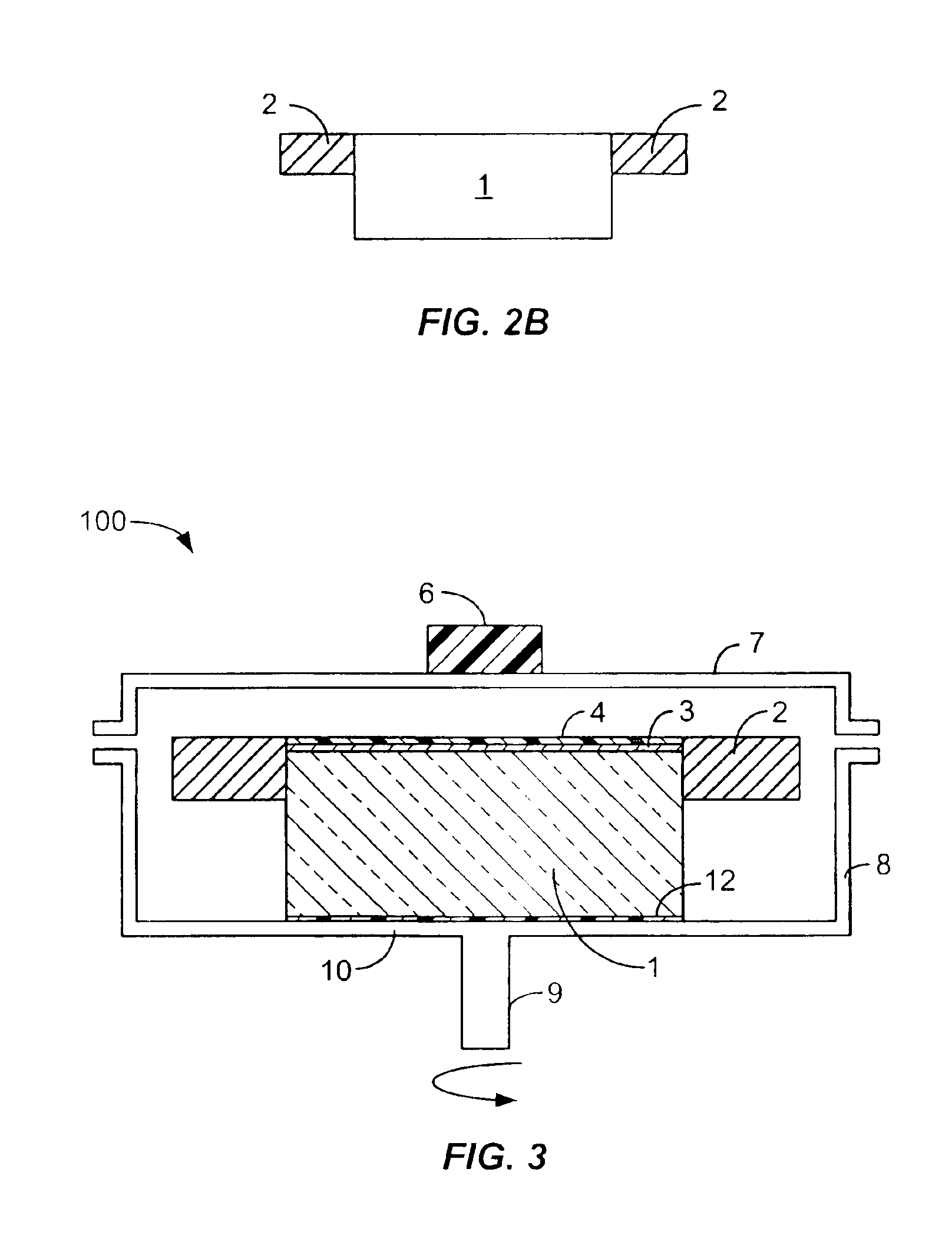
Referring to FIG. 1, the process according to the invention is illustrated. A glass substrate, such as a square block of BK-7 glass, is provided which has been provisioned with an anti-reflective (AR) coating on the uncoated bottom side, with gold coatings on its four lateral sides, and indium tin oxide (ITO) / SiO2 coatings on the topside (Step A). The ITO coating thoroughly covers between opposite sidewalls.

Referring to FIGS. 2A and 2B with 1, the substrate, which is typically a square glass block is placed into a converting fixture or collar 2 in order to convert the square surface into the equivalent of a round or enclosure-conforming substrate to accommodate the spin coating process (Step B). As shown in FIGS. 2A and 2B, a two-piece semi circular collar fixture 2 made of aluminum or other material is placed around the square BK-7 substrate 1. The fixture 2 is set so that its surface is at the same level as the top of the BK-7 substrate 1. The primary purpose of circularizing the ...


PUM

PropertyMeasurementUnit
thicknessaaaaaaaaaa
distanceaaaaaaaaaa
pressureaaaaaaaaaa

Abstract

Electro-optic structures are constructed by spin coating water based emulsions or solvent based sensor materials, preferably a solvent-based polymer dispersed liquid crystal (PDLC), onto a substrate under conditions of controlled solvent evaporation. In a particular process, the uniformity of the PDLC coating is achieved by 1) spin coating in a semi-sealed chamber, 2) “converting” a square substrate into round substrate by using a fixture; 3) providing a controllable distance between the substrate and a spin coater top cover; and 4) providing a controllable solvent evaporation rate.

Description

CROSS-REFERENCES TO RELATED APPLICATIONSNOT APPLICABLESTATEMENT AS TO RIGHTS TO INVENTIONS MADE UNDER FEDERALLY SPONSORED RESEARCH OR DEVELOPMENTNOT APPLICABLEREFERENCE TO A “SEQUENCE LISTING,” A TABLE, OR A COMPUTER PROGRAM LISTING APPENDIX SUBMITTED ON A COMPACT DISK.NOT APPLICABLEBACKGROUND OF THE INVENTIONThis invention relates to manufacturing processes for electro-optic modulators based on properties of polymer dispersed liquid crystal (PDLC) material for use in testing arrays of thin film transistors (TFT). More particularly, this invention relates to manufacturing processes involving solvent-based polymer dispersed liquid crystal (PDLC).Over the past decade, Photon Dynamics, Inc., of San Jose, Calif., has been manufacturing electro-optic modulators by an assembly process especially adapted to a class of raw material called NCAP involving a multi-step lamination process. Due to various complications, the result was relatively low yield of the final modulator. Problems include...

Claims


Application Information

Patent Timeline
Patent Type & Authority Patents(United States)
IPC IPC(8): G02F1/1334G02F1/13
CPCG02F1/1334B05D1/36G02F1/13
Inventor CHEN, XIANHAINAGY, ALEXANDER
Owner PHOTON DYNAMICS
Why Eureka
Try Eureka