Device for detecting three-dimensional shapes of elongated flexible body

a flexible body and three-dimensional technology, applied in the field of devices for detecting three-dimensional (3d) shapes and conditions of elongated flexible bodies, can solve the problem that the provision of perpendicularly intersecting x- and y-axes is not necessarily an imperative requisi

Inactive Publication Date: 2005-03-15
FUJI PHOTO OPTICAL CO LTD
View PDF3 Cites 167 Cited by
  • Summary
  • Abstract
  • Description
  • Claims
  • Application Information

AI Technical Summary

Benefits of technology

In view of the foregoing situations, it is an object of the present invention to provide a device which is simplified and compact in construction but capable of detecting three-dimensional shapes of an elongated flexible body like a flexible insertion tube of an endoscope without necessitating complicate signal processing.
The FBG sensor cable is applicable to an elongated flexible body which has an internal coextensive axial passage to place the sensor cable in. In use, the elongated flexible body is inserted into an internal cavity and invisible from outside like a flexible insertion tube of an endoscope. More specifically, in case the sensor cable is to be placed in an endoscopic biopsy channel for detection of three-dimensional shapes of a flexible insertion tube of an endoscope, it is desirable for the sensor cable to have an outside diameter close to the inside diameter of the biopsy channel, as long as placement of the sensor cable is not hindered by tightness.

Problems solved by technology

However, the provision of the perpendicularly intersecting X- and Y-axes is not necessarily an imperative requisite.

Method used


Image

  • Device for detecting three-dimensional shapes of elongated flexible body
  • Device for detecting three-dimensional shapes of elongated flexible body
  • Device for detecting three-dimensional shapes of elongated flexible body

Examples


second embodiment

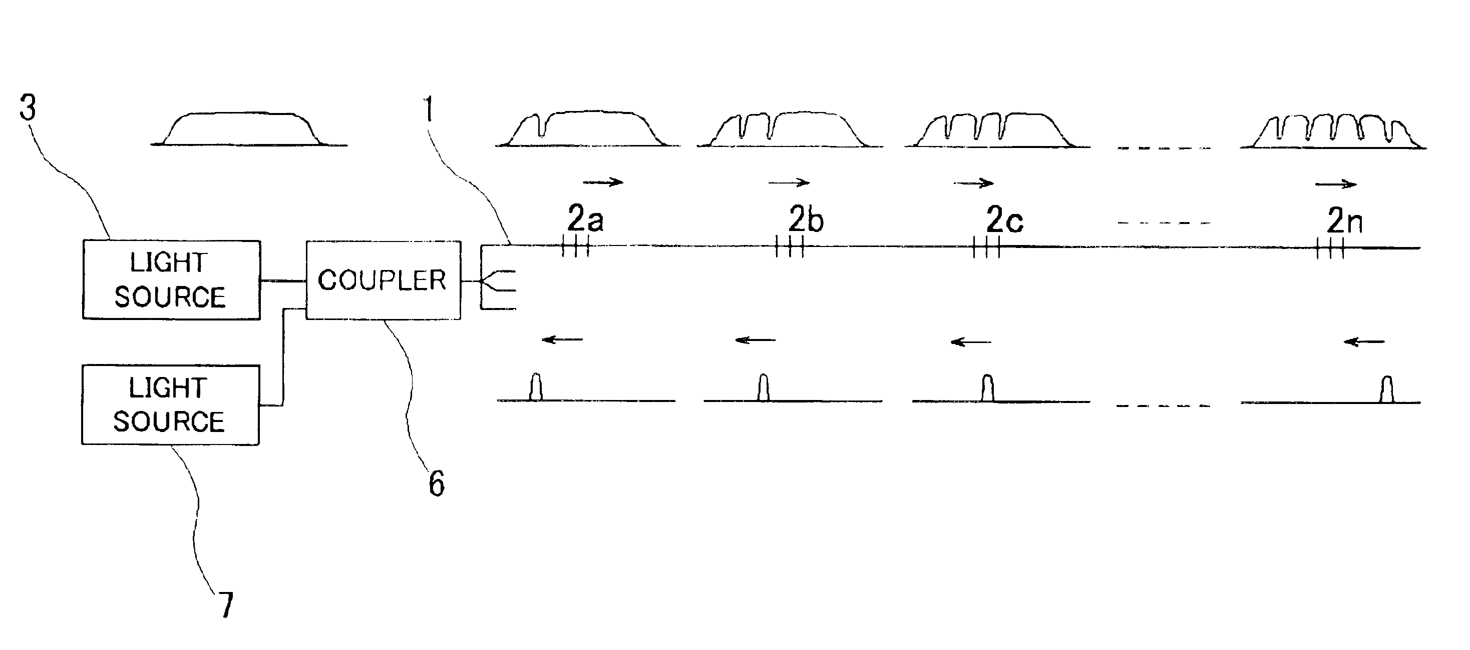
Turning now to FIG. 11, there is shown the present invention. In the case of this embodiment, all of the refractive index change sections 31 in a FBG strand 30 have the same refractive index. Accordingly, Bragg wavelength light, substantially consisting of a single wavelength, is projected from a light source 32. The light from the light source 32 is divided into a signal light beam to be fed to the FBG strand 30 and a reference light beam. The signal light is fed to the FBG 30 through a beam splitter 34 which is located in the path of the signal light. As a result, return signals of reflection diffraction light are obtained from the respective refractive index change portions 31. These return signals of reflection diffraction light are reflected off the beam splitter 34 and projected on a wave surface synthesizing beam splitter 35.

On the other hand, the reference light beam, which has been divided by the half mirror 33, is reflected off a reflecting mirror 36 to turn its light path...

first embodiment

Thus, by the variable length light path means 37, the length of the reference light path is sequentially adjusted to match the lengths of reflection diffraction light paths from the respective refractive index change portions 31 of the FBG strand 30. At the wave surface synthesizing beam splitter (or an optical circulator) 35, the reflection diffraction light from the FBG 31 is transmitted and the reference light is reflected off. In synthesizing the two wave surfaces, interference occur therebetween. Images of interference fringes are taken by a camera 39 to detect the extent of bending flexure at each one of the refractive index change portions 31 on the basis of the information of interference fringes. Namely, the greater the extent of flexure, the smaller becomes the interference fringe signal. Accordingly, three-dimensional shapes of an elongated flexible member like the endoscopic insertion tube 12 can be measured by the use of a sensor cable with four FBG strands in a manner ...


PUM


Abstract

For detecting three-dimensional shapes of an elongated flexible body, a sensor cable to be placed in a passage or channel which is formed axially and coextensively within the elongated flexible body. The sensor cable has two pairs of fiber Bragg grating strands within a tubular carrier casing. A signal light beam containing Bragg wavelength bands is projected from a light source to input same to refractive index change portions in the fiber Bragg grating strands. Reflection diffraction light signals from the refractive index change portions are received by a signal processor to measure the degree of strain at each one of the respective refractive index change portions by comparing wavelengths of the reflection diffraction light signals with reference wavelength.

Description

BACKGROUND OF THE INVENTION1. Field of the ArtThis invention relates to a device for detecting three-dimensional (3D) shapes and conditions of an elongated flexible body, for example, 3D shapes and conditions of bends in an endoscopic flexible insertion tube which has been introduced into a body cavity of a patient.2. Prior ArtFor instance, in the case of an endoscope for examination of lower digestive ducts, its insertion tube needs to be inserted into through a complicate path of insertion which contains three-dimensional bends, more specifically, through the intestinum rectum, sigmoid colon, and lower, transverse and ascending colons. Besides, the path of insertion is not always maintained in stable conditions and can easily change into different conditions upon application of an external force. Therefore, as the insertion tube is inserted along a path of insertion, in some cases the fore leading end of the insertion tube is pushed against an intracavitary wall portion and stuck ...

Claims


Application Information

Patent Timeline
Patent Type & Authority Patents(United States)
IPC IPC(8): A61B5/06A61B1/00G01B11/24G01D5/353G02B5/18G02B6/00
CPCA61B1/0055A61B5/06A61B5/065A61B5/061G02B6/02057A61B2019/5261A61B2034/2061A61B1/009
Inventor FUJITA, HIROSHI
Owner FUJI PHOTO OPTICAL CO LTD
Why Eureka
Try Eureka