Method for fabricating chirped fiber Bragg gratings

a technology of chirped fiber bragg grating and grating plate, which is applied in the direction of photomechanical equipment, instruments, originals for photomechanical treatment, etc., can solve the problems of inability to achieve the accuracy necessary, difficult and time-consuming fabrication of such gratings, and inability to achieve the effect of accurate stitching in the mask pattern, reducing throughput overhead, and reducing production times

Inactive Publication Date: 2005-03-15
PHOTRONICS INC
View PDF7 Cites 4 Cited by
  • Summary
  • Abstract
  • Description
  • Claims
  • Application Information

AI Technical Summary

Benefits of technology

In accordance with the invention, a phase mask for a chirped fiber Bragg grating defined by a series of scale factors is made without repeated recalibrations, thereby reducing throughput overhead. Instead, the scale factors are converted into correction factors, or alpha corrections for each segment. The position of each segment in the array that comprises the mask is adjusted to compensate for shifts in segment position due to application of the correction factor. This adjustment can be made following the selection of a fixed “center point” from which the correction factor is measured in order to assure accurate stitching in the mask pattern.
Thus, the phase mask for the chirped fiber Bragg grating is made in the customary manner by exposing a photoresist-coated substrate to an electron beam or other lithographic instrument which writes the mask pattern into the substrate which is then developed and etched. The resulting phase mask is used to write a chirped Bragg grating into an optical fiber. However, by utilizing a correction factor at the segment level to produce successive pitch changes in the mask, it is no longer necessary to redefine the base writing unit for each segment. Due to dramatically reduced production times, the application of a multipass write strategy results in a highly accurate phase mask produced lithographically within an improved write time.

Problems solved by technology

Although the characteristics of chirped fiber Bragg gratings are desirable, fabrication of such gratings has proven difficult and time-consuming.
Particularly, the fabrication of chirped phase masks has been challenging.
Conventional lithography tools such as an electron beam (e-beam) tool (for example, the MEBES III or MEBES 4500, both manufactured by Applied Materials, Inc. of Santa Clara, Calif.) have been unable to achieve the accuracy necessary to produce a phase mask for a chirped Bragg grating in a time period that makes them competitive.
On a MEBES tool in particular, phase mask fabrication has been attempted using a “scale factor” approach and is therefore particularly complex.
This time consuming step is necessary whenever the base writing unit is changed.
Unfortunately, despite minimizing throughput overhead added due to recalibration of the MEBES tool to its minimum, the repetition of steps 30a-30d still requires that for each successive segment the base writing unit must be redefined to correspond to the new scale factor for that segment.
This disadvantage can result in fabrication times for a typical 200 segment chirped Bragg grating phase mask to be over 8 hours.
Additionally, the technique is not sufficiently accurate for many fiber Bragg grating applications.
Stitching and pitch errors have been observed using the scale factor method that result in phase errors and unacceptable levels of a phenomenon known as group delay ripple (GDR) in the chirped Bragg grating ultimately printed on the fiber using the mask.
Although methods such as the multipass strategy achieve achieving a sufficiently low GDR value in a mask produced by an e-beam or similar lithography tool, application of the technique is rendered commercially impossible using the method of the prior art.
Although other lithography tools may have different write times, the effect of repeated recalibration of basic operational units is similarly time-consuming.

Method used


Image

  • Method for fabricating chirped fiber Bragg gratings
  • Method for fabricating chirped fiber Bragg gratings
  • Method for fabricating chirped fiber Bragg gratings

Examples


Embodiment Construction

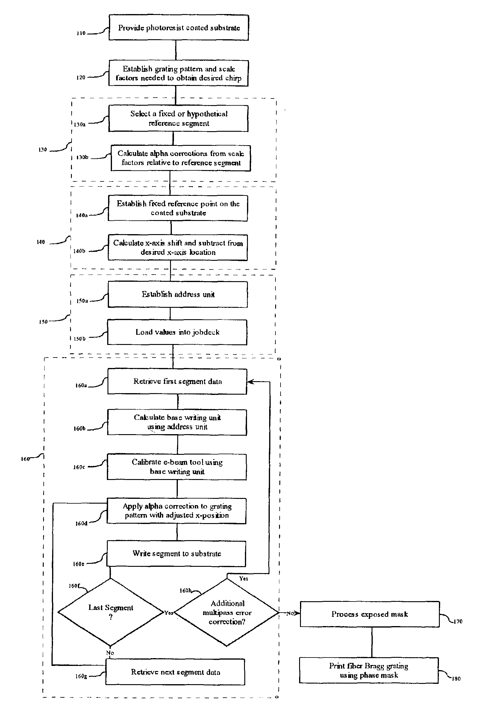
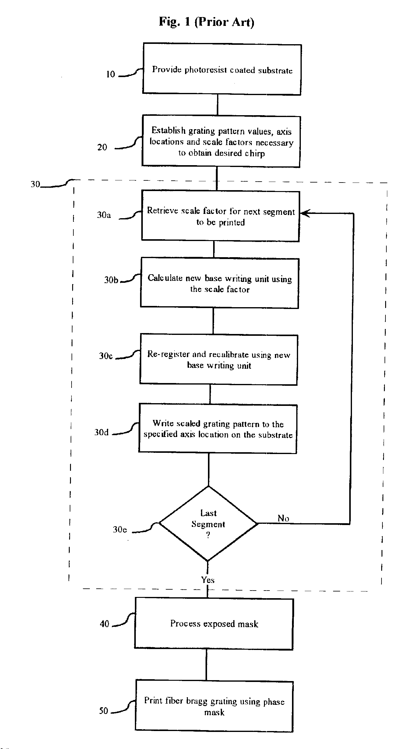
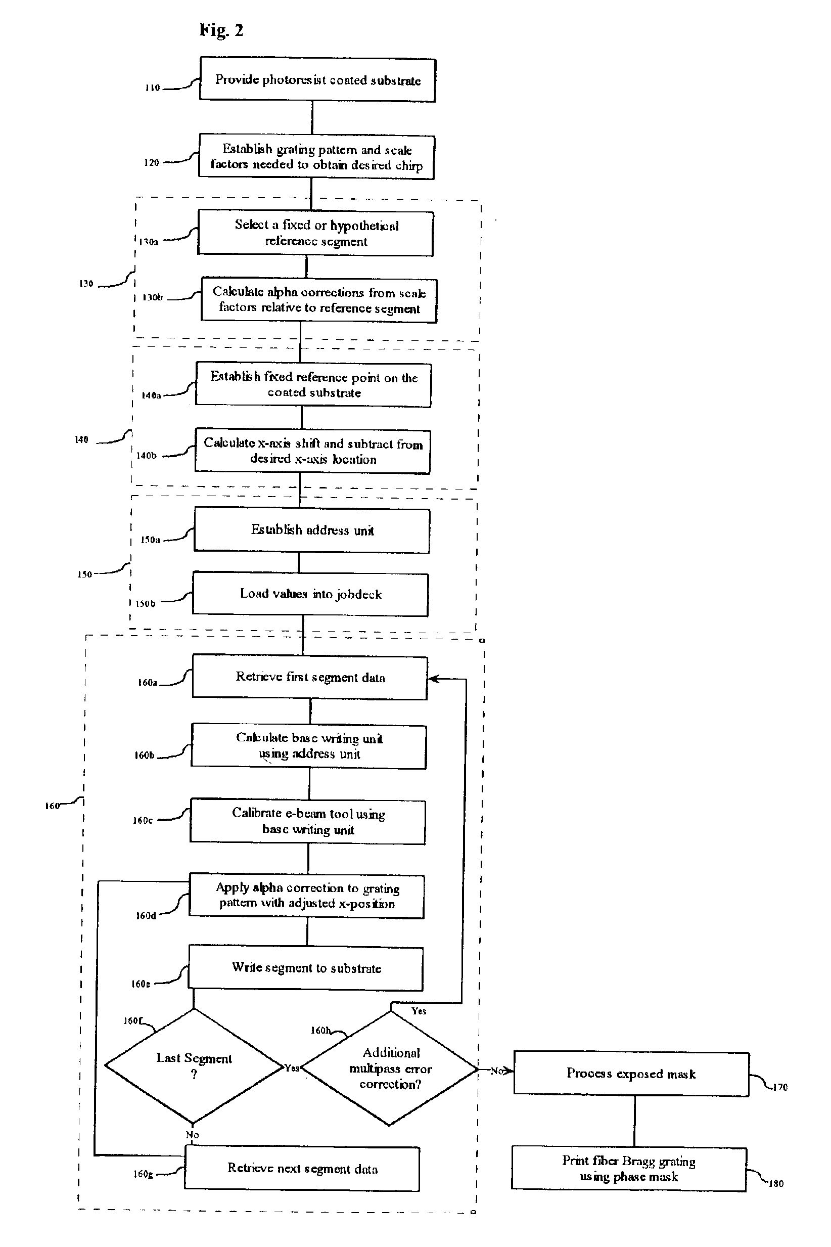
The present invention is generally directed to a method for achieving scale changes for a writing element in a lithography tool. More particularly, the present invention is directed to a method for producing chirped fiber Bragg grading using a lithography tool wherein correction factors, rather than conventional scale factors, are used for achieving scale changes for a writing element. One example of the implementation of the present invention is illustrated in FIG. 2. FIG. 2 is a block diagram illustrating the steps in making a chirped fiber Bragg grating on lithography tool such as the MEBES 4500 e-beam tool or similar lithographic tool using the improved machine control method of the present invention. As in the method of the prior art given in FIG. 1, a photoresist coated substrate is loaded onto the stage of the lithography tool, and an appropriate grating pattern and scale factors are chosen as shown in FIG. 2 at 110 and 120 respectively.

The grating pattern may be a series of ...


PUM

PropertyMeasurementUnit
lengthaaaaaaaaaa
lengthaaaaaaaaaa
widthaaaaaaaaaa

Abstract

A chirped Bragg grating is fabricated in an optical fiber by exposing the fiber to a coherent beam of light through a parallel phase mask having a series of progressively chirped segments produced on a lithography tool. The chirped phase mask is fabricated by exposing a photoresist-coated substrate to an image writing element such as an electron beam or a laser according to a set of parameters provided to the lithography tool. The parameters include a basic grating pattern for each segment, a value that defines the expansion or contraction of the grating pattern and an axis location to which the grating pattern is to be written to the substrate. By selecting machine commands that implement these parameters with a minimum throughput overhead, the mask can be produced in a reduced time, and therefore with increased accuracy.

Description

FIELD OF THE INVENTIONThis invention relates to optical fiber Bragg gratings and, in particular to an improved method for writing masks for use in fabricating in-fiber chirped Bragg gratings.BACKGROUND OF THE INVENTIONOptical fibers are essential components in modern telecommunications systems. Comprised of thin strands of glass, optical fibers enable the transmission of light, or optical signals, over long distances with little loss. An optical fiber typically has a core of glass having a specific index of refraction surrounded by a glass cladding having a lower index of refraction. Thus, light entering the fiber is retained within the core by internal reflection.In applications wherein a single optical fiber carries signals on more than one wavelength, such as in wavelength division multiplexing (WDM), fiber Bragg gratings are used for controlling the specific wavelengths of light within the fiber. Fiber Bragg gratings also have other applications such as in fiber lasers. A typica...

Claims


Application Information

Patent Timeline
Patent Type & Authority Patents(United States)
IPC IPC(8): G02B6/02G03F1/14G03F7/40G03F1/34G03F7/00
CPCG02B6/02085G03F7/0005G03F1/34G02B6/02138
Inventor UNRUH, JAMES OWEN
Owner PHOTRONICS INC
Why Eureka
Try Eureka