Method of determining the volume scattering function of ocean waters in the backward direction using a satellite ocean color sensor
- Summary
- Abstract
- Description
- Claims
- Application Information
AI Technical Summary
Benefits of technology
Problems solved by technology
Method used
Image
Examples
example 1
CALCULATING THE SHARPNESS OF THE FIELD OF VIEW (FOV) CONE ANGLE SUBTENDED BY AN OCEAN PIXEL AT THE SATELLITE DETECTOR PIXELS
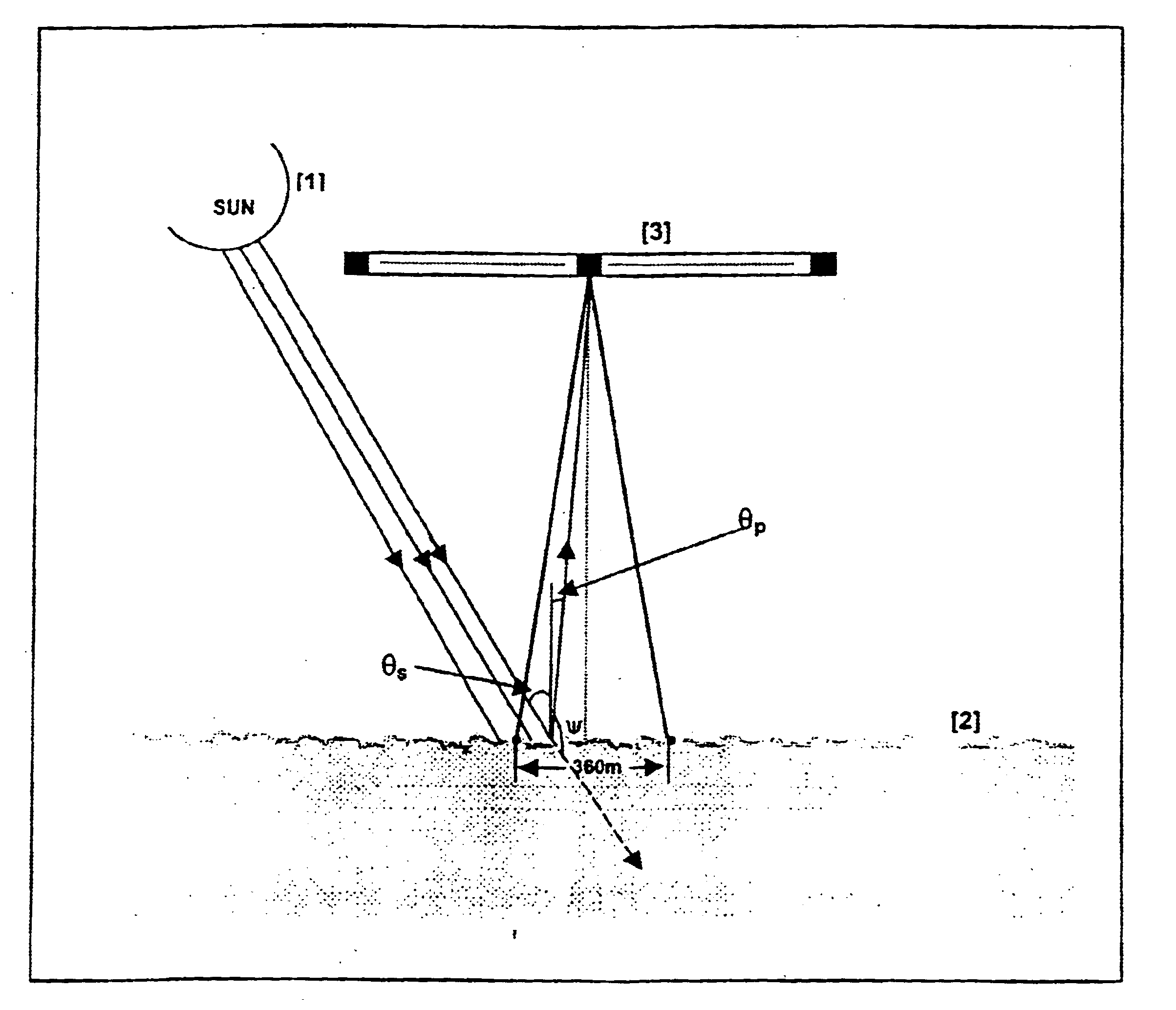
This one-time calculation demonstrates that the FOV subtended by a pixel on the ocean surface is extremely narrow, thus simplifying the method of computing the backward VSF by space sensors. Using the parameters in Table 1, we assume an ocean pixel of area 360 m×236 m and a satellite altitude of 720 kms. The solid angle subtended by an off-centre ocean pixel of area 360 m×236 m at the satellite detector height H (=720 kms) is given by:
dΩ=[360×236 cos θp] / [H2] [1]
Calculation shows that the solid angles are of the order of <=2.5 mrads for look angles θp in the range +43° to −43. These are extremely narrow FOV angles, and it is safe to assume that the pixel cone can be replaced by a straight line from the centroid of the ocean pixel to the CCD pixel on the satellite detector.
example 2
CALCULATING THE SCATTERING ANGLE ψ OF THE BACKWARD VOLUME SCATTERING FUNCTION β(ψ,λ) AT A GIVEN WAVELENGTH
The OCM sensor on the IRS-P4 satellite consists of eight CCD line array detectors, each of which view the backscattered radiation in the eight wavebands shown in Table 1. At any given instant of time, the CCD pixels on a detector view a scan line of ocean pixels arranged along a 1420 km swath of the ocean surface as shown in FIG. 3. Each of the 3730 CCD detector pixels is associated with a look angle θp, which have values lying in the range +43° of the fan shaped cone shown in FIG. 3. Simple geometric anaysis of the representation in FIG. 4 shows that the scattering angle ψ can be defined as the angle between the extended solar ray direction and the direction of the backscattered water leaving radiance emerging at the look angle θp to the zenith direction by:
ψ=[180−(θp+θs)] [2]
Given the simple geometric relation in [2], and assuming θs˜17° as a typical solar angle shows that ψ ...
example 3
CORRECTING THE LOOK ANGLE θp OF A CCD PIXEL ON AN OCEAN PIXEL
The look angle θp of a CCD pixel on the satellite sensor is measured with respect to the zenith direction. However, a correction needs to be applied to this parameter by the relation (see A. Morel, J. L. Mueller, “Normalised Water-Leaving Radiance and Remote Sensing Reflectance: Bi-directional Reflectance and other factors “in Ocean Optics Protocols for satellite Ocean Color Sensor Validation, Rev. 3, Vol 2, pp 183-210, 2002)
θp=θsat+sin−1(0.113 tan θsat) [3]
The angle θsat refers to the satellite view angle, and this is available in most satellite data processing packages for Ocean Color sensors
PUM
| Property | Measurement | Unit |
|---|---|---|
| wavelength | aaaaa | aaaaa |
| width | aaaaa | aaaaa |
| half angle | aaaaa | aaaaa |
Abstract
Description
Claims
Application Information
 - R&D
- Intellectual Property
- Life Sciences
- Materials
- Tech Scout
- Unparalleled Data Quality
- Higher Quality Content
- 60% Fewer Hallucinations
Browse by: Latest US Patents, China's latest patents, Technical Efficacy Thesaurus, Application Domain, Technology Topic, Popular Technical Reports.
© 2025 PatSnap. All rights reserved.Legal|Privacy policy|Modern Slavery Act Transparency Statement|Sitemap|About US| Contact US: help@patsnap.com


