Joined structures of metal terminals and ceramic members, joined structures of metal members and ceramic members, and adhesive materials

a technology of metal terminals and ceramic members, applied in the direction of textiles and paper, solid-state devices, non-electric welding apparatus, etc., can solve the problems of cracks in ceramic members near the inner wall surface, reducing production yield, and cooling the ceramic member step, and achieve the effect of high bonding strength

Inactive Publication Date: 2005-03-22
NGK INSULATORS LTD
View PDF8 Cites 6 Cited by
  • Summary
  • Abstract
  • Description
  • Claims
  • Application Information

AI Technical Summary

Benefits of technology

According to the present invention, a ceramic member and a metal member may be joined with each other with a sufficiently high bonding strength and without crack formation in the ceramic material constituting the ceramic member.

Problems solved by technology

In an actual production line, however, some problems were found in the step of cooling the ceramic member to room temperature after the brazing (heating) step.
That is, cracks may occur in the ceramic member near the inner wall surface, particularly near the corner portions of the hollow of the ceramic member.
Such cracks result in off-specification products and reduce the production yield.

Method used


Image

  • Joined structures of metal terminals and ceramic members, joined structures of metal members and ceramic members, and adhesive materials
  • Joined structures of metal terminals and ceramic members, joined structures of metal members and ceramic members, and adhesive materials
  • Joined structures of metal terminals and ceramic members, joined structures of metal members and ceramic members, and adhesive materials

Examples


experiment a

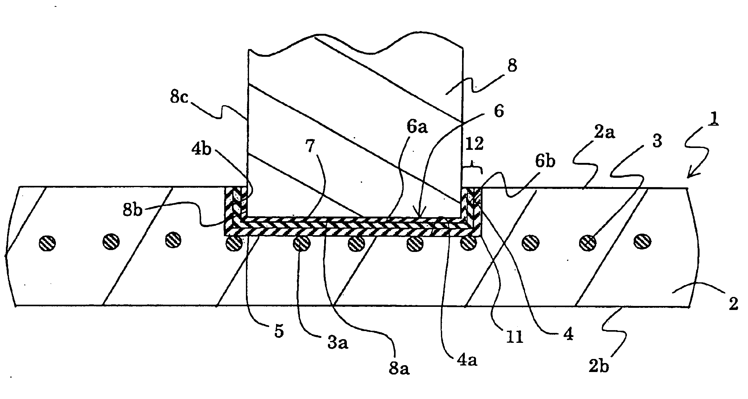
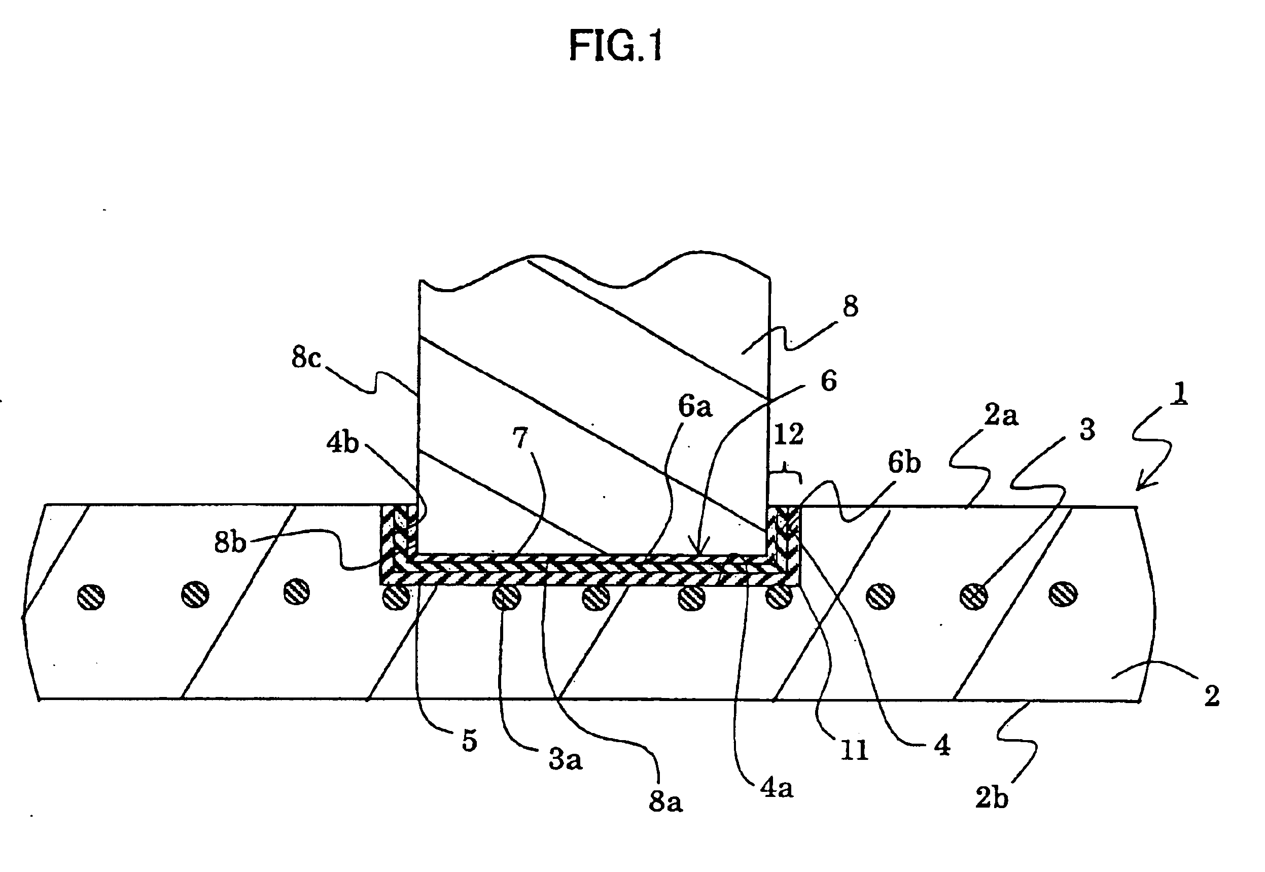
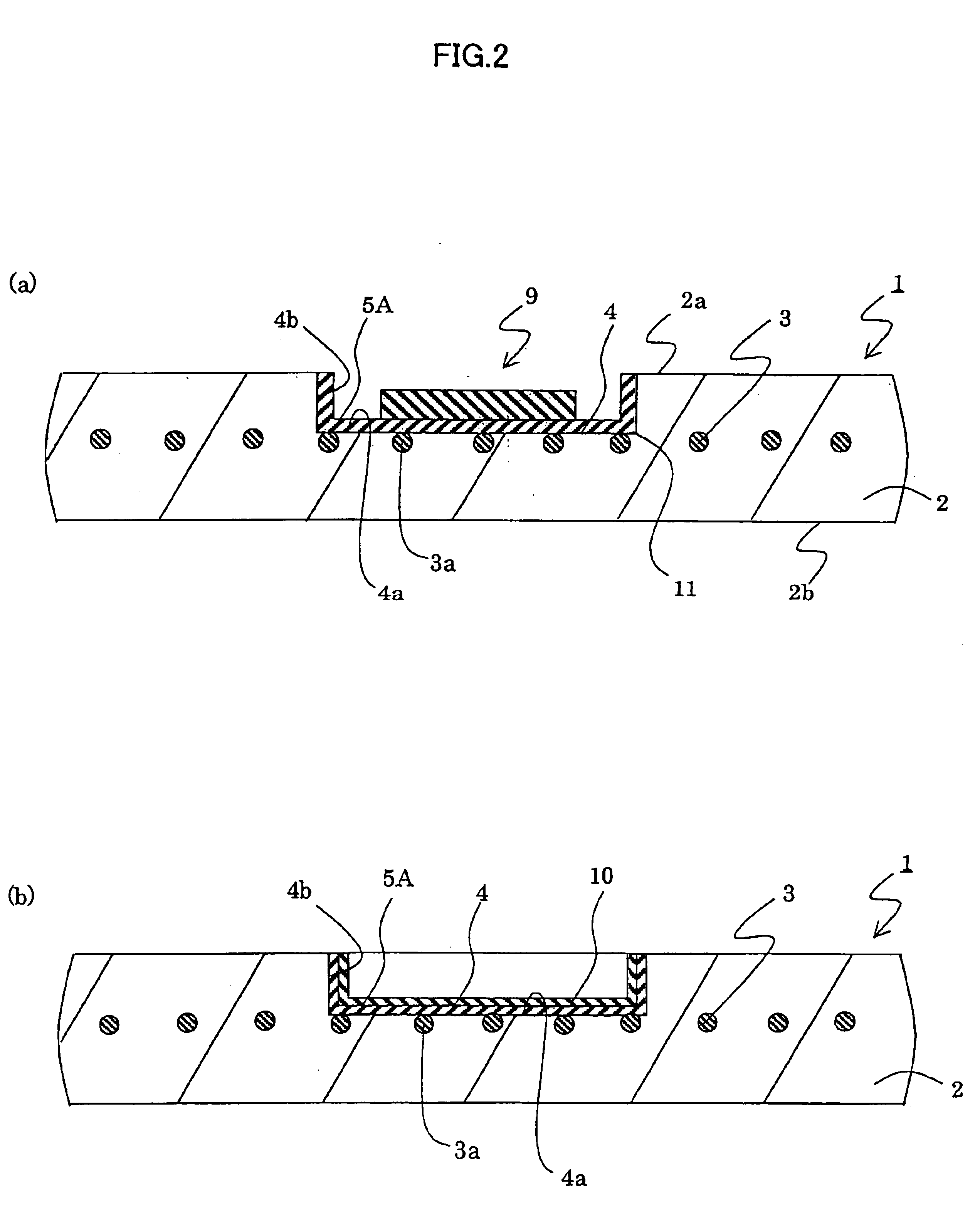
A ceramic electrostatic chuck was produced and a sample for a tensile test was cut therefrom. That is, aluminum nitride powder was filled in a mold and sealed with a carbon foil. A metal mesh was embedded in the aluminum nitride powder. The mesh is obtained by knitting molybdenum wires having a diameter of 0.12 mm at a density of 50 wires per inch. The aluminum nitride powder with the mesh therein was hot press sintered to a maximum temperature of 1950° C. under a pressure of 200 kg / cm2 for a holding time period of 2 hours at 1950° C. to produce a sintered body. The sintered body had a relative density of not lower than 98.0 percent. The mesh was embedded within the sintered body so that the mesh may function as an electrode for electrostatic chuck. A ceramic member, with a length of 20 mm, a width of 20 mm and a thickness of 2 mm, was cut out from the sintered body. A circular hollow 4 with a diameter of 6 mm and a depth of 1 mm was formed in the central portion of the ceramic memb...

experiment b

The same ceramic member and metal terminal as those used in Experiment A were joined with each other to produce four samples. However, the following three conditions were different from those applied in Experiment A. That is, an aluminum solder was used, and the solder was heated at 610° C. and under vacuum. Consequently, cracks were confirmed by visual evaluation within AlN in all of the four samples.

experiment c

The same ceramic member and metal terminal as those used in Experiment A were joined with each other to produce four samples. However, the following three conditions were different from those applied in Experiment A. That is, a solder of Ag—Cu—Ti system was used, and the solder was heated at 850° C. and under vacuum. Consequently, cracks were confirmed by visual evaluation within AlN in all of the four samples.


PUM

PropertyMeasurementUnit
weight percentaaaaaaaaaa
melting pointaaaaaaaaaa

Abstract

A joined structure of a metal terminal and a ceramic member has a joining layer between the terminal and the ceramic member. The joining layer has a metal adhesive layer containing at least indium metal. The invention further provides a joined structure of a metal member and a ceramic member. The metal member has a tip face and a side face. A hollow is formed in the ceramic member. A joining layer is formed between a bottom surface facing the hollow and the tip face of the member, and further formed between a side wall surface facing the hollow and the side face of the member. The joining layer has a metal adhesive layer containing at least indium metal.

Description

BACKGROUND OF THE INVENTIONThe present invention relates to a joined structure of a metal member, particularly metal terminal, and a ceramic member, and an adhesive material therefor.Dense ceramics are noted as a base material for an electrostatic chuck. In the field of semiconductor producing systems, electrostatic chucks have been practically used as susceptors containing an electrode for applying high frequency power to generate plasma. In such a device for applying high frequency power, the electrode for applying high frequency power has been embedded in a substrate made of silicon nitride or alumina.In such devices, it is necessary to embed a metal electrode in a ceramic substrate such as aluminum nitride, alumina or the like and to electrically connect the metal electrode to an outer connector for supplying electric power. The Applicants disclosed a process of producing a ceramic heater, an electrostatic chuck and an electrode system for applying high frequency voltage used fo...

Claims


Application Information

Patent Timeline
Patent Type & Authority Patents(United States)
IPC IPC(8): H01R4/58H01R4/62H01R39/00H01R39/02H01R4/00H01R4/04B23K1/19B23K101/36C04B37/02H01L21/683B23K1/00
CPCH01R4/62H01R4/04Y10T428/12375H01R39/022H01R39/027H01L2924/0002Y10T428/12528Y10T428/12535Y10T428/12868Y10T428/12486Y10T428/198Y10T428/12681Y10T428/12493H01L2924/00C04B35/581C04B35/645C04B37/026C04B2235/77C04B2235/96C04B2237/12C04B2237/121C04B2237/123C04B2237/125C04B2237/343C04B2237/40C04B2237/68C04B2237/708C04B2237/72C04B2237/84Y10T428/31678
Inventor FUJII, TOMOYUKIOHTA, MITSURUOHASHI, TSUNEAKI
Owner NGK INSULATORS LTD
Why Eureka
Try Eureka