In situ application of etch back for improved deposition into high-aspect-ratio features

Inactive Publication Date: 2005-03-22
APPLIED MATERIALS INC
View PDF55 Cites 235 Cited by
  • Summary
  • Abstract
  • Description
  • Claims
  • Application Information

AI Technical Summary

Benefits of technology

In other embodiments, the first deposition phase may be combined with the etch phase of the process by providing a gaseous mixture to the process chamber that includes both a deposition gas and an etchant gas. A plasma is generated from the gaseous mixture with a plasma coupling structure to simultaneously deposit a first portion of the film on the substrate and etch the film. The plasma includes

Problems solved by technology

Gaps having a combination of a high aspect ratio and a small width present a challenge for semiconductor manufacturers to fill completely.
In short, the challenge usually is to prevent the deposited film from growing in a manner that closes off the gap before it is filled.
Failure to fill the gap completely results in the formation of voids in the deposited layer, which may adversely affect device operation, such as by trapping undesirable impurities.
Notably, while there has been some recognition that in situ etch processes may be desirable for dep/etch/dep processes, in practice attempts at such processes have been constrained by limitations in

Method used


Image

  • In situ application of etch back for improved deposition into high-aspect-ratio features
  • In situ application of etch back for improved deposition into high-aspect-ratio features
  • In situ application of etch back for improved deposition into high-aspect-ratio features

Examples


Example

1. Introduction

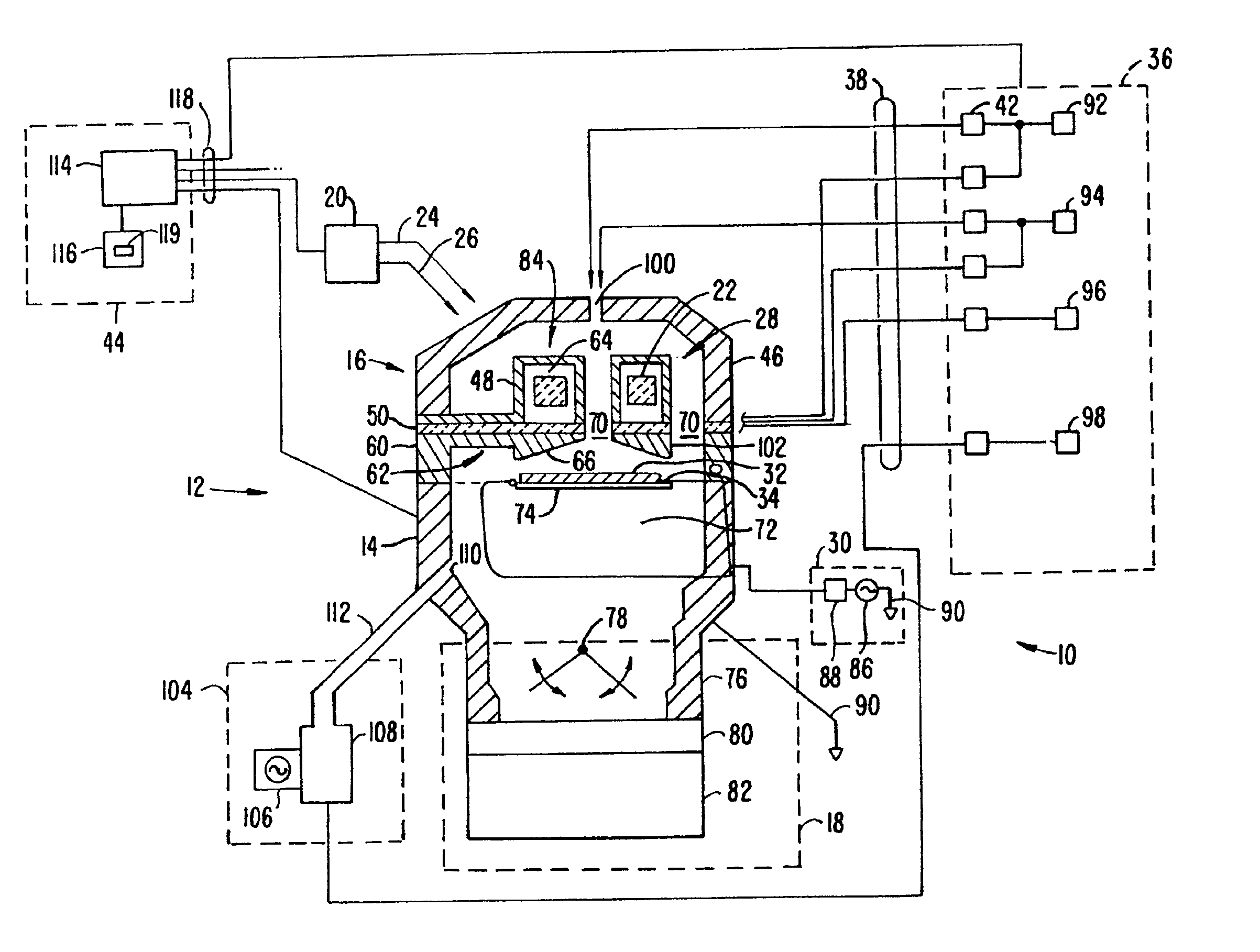
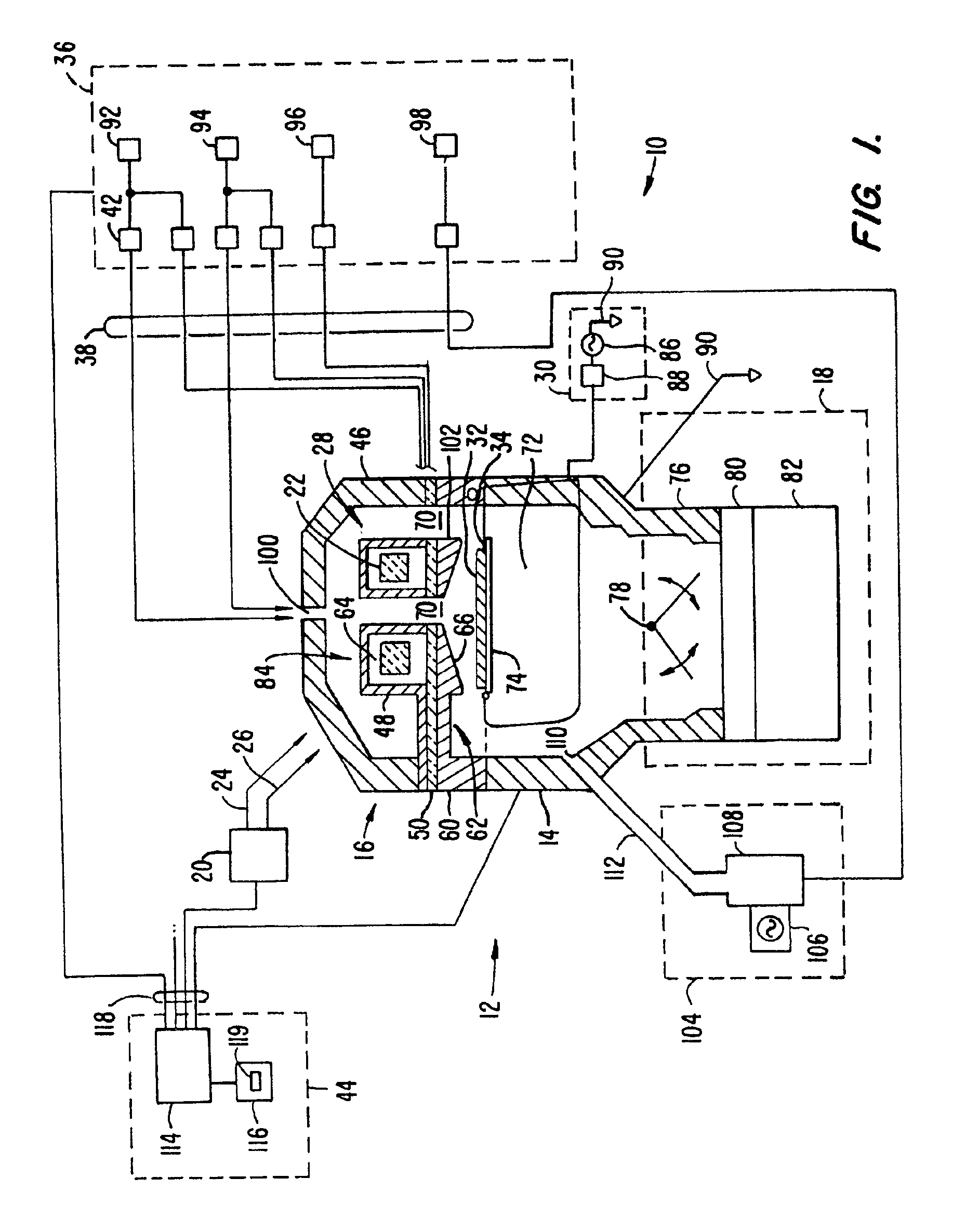
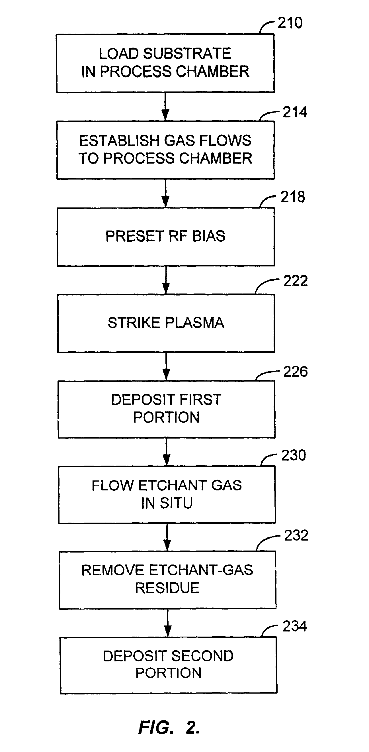
Embodiments of the invention use a continuous in situ plasma for all phases of a dep / etch / dep process. This is achieved with a chamber design that disposes the plasma source, which may be a toroidal plasma source, within the process chamber. Such a design and process have a number of advantages. For example, the chamber design is especially suitable for processes that use etchant gases because it does not include a capacitive coupling between the dome and plasma-generation coils. This allows in situ processing with etchants while avoiding undesirable surface erosion within the process chamber. This process is unlike previous dep / etch / dep processes, which were instead generally adapted for remote-plasma etch phases; attempts to adapt those processes to in situ etch phases resulted in the deficiencies described above.

In embodiments of the invention, the dep / etch / dep process is accordingly performed as a continuous process without the need for separate plasma generation ...


PUM

PropertyMeasurementUnit
Densityaaaaaaaaaa
Ratioaaaaaaaaaa
Deposition rateaaaaaaaaaa

Abstract

A continuous in situ process of deposition, etching, and deposition is provided for forming a film on a substrate using a plasma process. The etch-back may be performed without separate plasma activation of the etchant gas. The sequence of deposition, etching, and deposition permits features with high aspect ratios to be filled, while the continuity of the process results in improved uniformity.

Description

BACKGROUND OF THE INVENTIONOne of the primary steps in the fabrication of modern semiconductor devices is the formation of a thin film on a semiconductor substrate by chemical reaction of gases. Such a deposition process is referred to as chemical vapor deposition (“CVD”). Conventional thermal CVD processes supply reactive gases to the substrate surface where heat-induced chemical reactions take place to produce a desired film. Plasma-enhanced CVD (“PECVD”) techniques, on the other hand, promote excitation and / or dissociation of the reactant gases by the application of radio-frequency (“RF”) energy to a reaction zone near the substrate surface, thereby creating a plasma. The high reactivity of the species in the plasma reduces the energy required for a chemical reaction to take place, and thus lowers the temperature required for such CVD processes as compared to conventional thermal CVD processes. These advantages are further exploited by high-density-plasma (“HDP”) CVD techniques, ...

Claims


Application Information

Patent Timeline
IPC IPC(8): C23C16/04C30B25/10C23C16/50C23C16/509H01L21/70H01L21/02H01L21/768H01L21/311H01L21/316C23C16/44C23C16/455
CPCC23C16/045C23C16/45523C23C16/509C30B25/105H01L21/76837H01L21/02164H01L21/02274H01L21/31116H01L21/31612H01J37/32935
Inventor KRISHNARAJ, PADMANABHANIONOV, PAVELLAI, CANFENGCOX, MICHAEL SANTIAGOSHAMOUILIAN, SHAMOUIL
Owner APPLIED MATERIALS INC
Why Eureka
Try Eureka