Multi-pass configurations

a multi-pass configuration and configuration technology, applied in multiplex communication, instruments, optical elements, etc., can solve problems such as beam broadening, and achieve the effect of reducing signal loss

Inactive Publication Date: 2005-03-22
JDS UNIPHASE INC
View PDF8 Cites 9 Cited by
  • Summary
  • Abstract
  • Description
  • Claims
  • Application Information

AI Technical Summary

Benefits of technology

In the present invention, yet another objective is achieved by utilizing etalon filters that fully reflect all of the incident light over the wavelength range of interest corresponding to the optical signal channels utilized, in combination with other reflective elements to provide a desirable level of chromatic dispersion compensation.
In accordance with another aspect of the invention a method for compensating dispersion in an optical signal is provided, comprising the steps of: providing a first optical filter having a single-sloped or monotonically sloped dispersion output response within at least a predetermined wavelength band; providing a second optical filter having a single-sloped or monotonically sloped dispersion output response within at least a predetermined wavelength band, wherein the first and second filters have slopes of opposite sign; tuning one of the first and second filters in a controllable manner to vary the amount of dispersion induced by the filter within the predetermined wavelength band with minimal signal loss over the tuning range.
In yet another aspect of the invention the device includes either multiple etalon filters to provide for either self-correction of the aforementioned beam-broadening phenomenon or to achieve a greater level of dispersion compensation with minimal signal loss over the tuning range.
Advantageously, the apparatus in accordance with the invention has a low loss and is independent to differences in a wavelength dependent optical path.

Problems solved by technology

As it has been recognized that the coupling losses arising from the use of the aforementioned multilayer optical filters may arise by an undesirable increase of the incident optical beam cross-section in at least one dimension which may be alternatively characterized as beam broadening, the first object is achieved by arranging optical filters, including etalon type filters, with other reflective elements such that the undesirable beam broadening, due to wavelength selective “walk off” is self-correcting and that the return optical path to the output port of such devices is substantially symmetric to the input optical path that results in beam broadening.

Method used


Image

  • Multi-pass configurations
  • Multi-pass configurations
  • Multi-pass configurations

Examples


embodiment 400

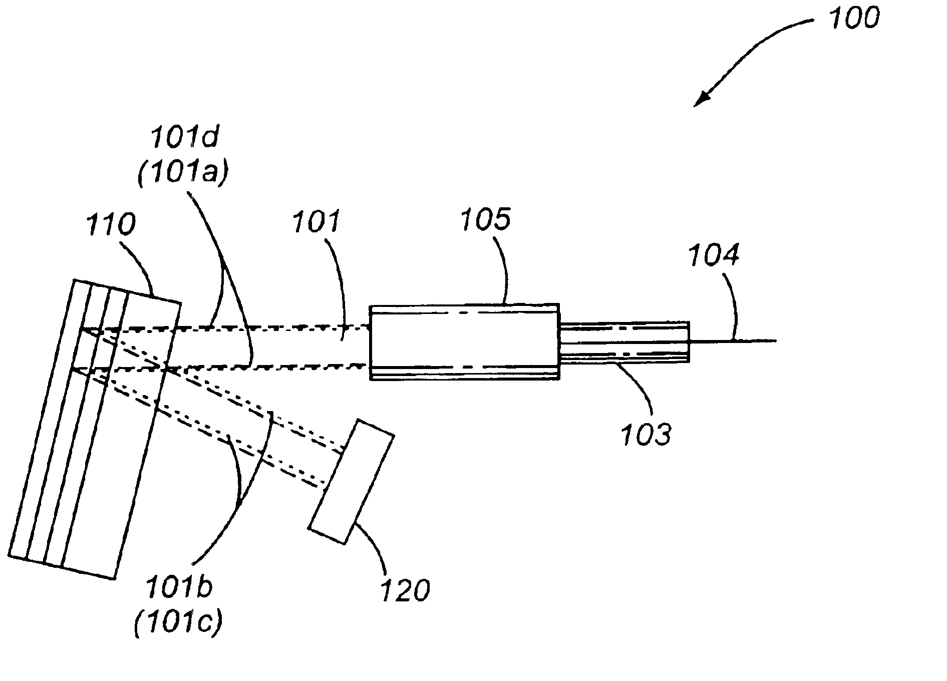
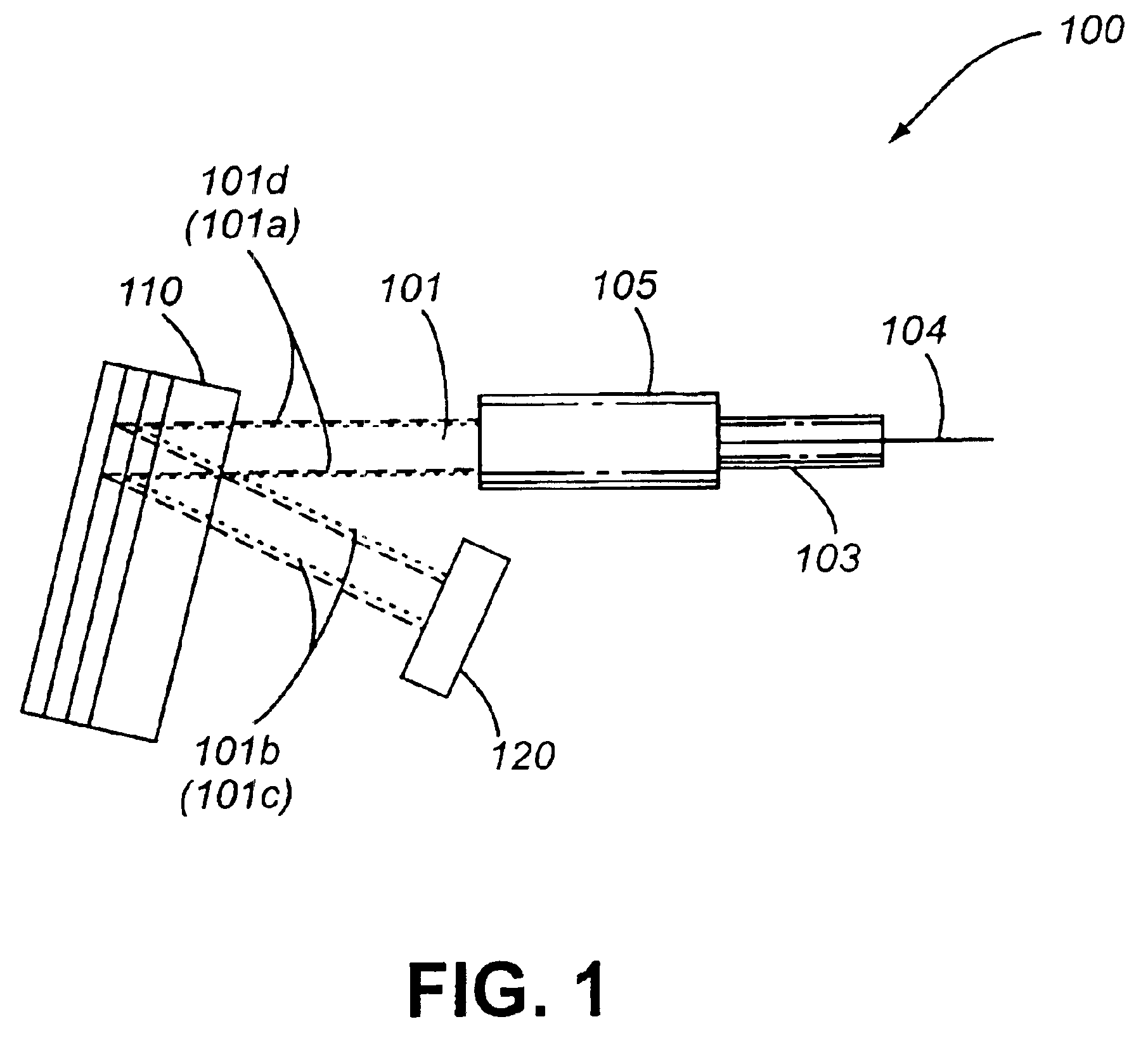
Another embodiment 400 of the invention is illustrated in FIG. 4 and includes an optical fiber 404 encased in a ferrule 403, which is coupled to a lens 405. This embodiment may be characterized as a (2:1)(1:1):1 device, as a second MLIF filter 411 replaces mirror 120 in FIG. 1, and is organized with respect to a first MLIF 410 such that optical beam segment 401b arrives at normal incidence. Accordingly the reversal of optical beam segment 401c results in a reduction in beam cross sectional dimension after the second reflection off first MLIF 411 such that the optical beam segment 401d has substantially the same cross sectional dimensions as optical beam segment 401a. This configuration allows for wavelength and non-wavelength dependent modification or selective routing of optical signal channels contained in optical beam 401, including chromatic dispersion compensation for group delay when first multilayer optical interference filter 410 is an etalon structure, as well as the combin...


PUM


Abstract

A method and device is disclosed for relaying a narrow diameter collimated optical beam carrying optical communication signal channels between a multilayer interference filters and another reflective surface avoiding signal loss by routing the optical beam to compensate for beam broadening caused by the multilayer interference filter. The method and device are particularly applicable to dispersion compensating filters, especially those wherein one filter is tunable, in that a controllable amount of dispersion is introduced to offset or compensate dispersion. Preferably one of the filters is a tunable periodic device in the form of a multi-cavity etalon structure. In a preferred embodiment of the filters can be designed to provide various controllable but different constant amounts of dispersion.

Description

MICROFICHE APPENDIXNot ApplicableBACKGROUND OF THE INVENTIONThe present invention relates to components for optical communications systems, specifically for interconnection and coupling devices utilizing multilayer optical interference filters.Optical communications systems comprise an interconnected network of optical fibers for transmitting a plurality of the optical signal channels between nodes in the network. In order to increase the capacity of existing optical communications systems, or provide for flexible reconfiguration, multiple optical signal channels may propagate between nodes simultaneously using time division and wavelength division multiplexing (WDM). Wavelength division multiplexing refers to a plurality of signal channels characterized by a different wavelength of light, while time division multiplexing refers to a time sequence allocation of digital signals within a common optical signal channel. Although information may be transmitted in analog format in a WDM s...

Claims


Application Information

Patent Timeline
Patent Type & Authority Patents(United States)
IPC IPC(8): G02B26/00G02B6/32G02B6/34G02B5/28H04B10/18H04J14/02
CPCG02B6/29358G02B6/29361G02B6/29394G02B26/001G02B6/32G02B6/29395G02B6/29398
Inventor RANDALL, GEOFFCOLBOURNE, PAULMOSS, DAVIDLAMONT, MICHAEL R. E.MCLAUGHLIN, SHELDON
Owner JDS UNIPHASE INC
Why Eureka
Try Eureka