Video decoder

a video decoder and video technology, applied in the field of video decoders, can solve the problems of increased power consumption of frame buffers b>104/b> with high operation frequency, inability to process pictures in mpeg decode cores, and increased power consumption of rambus dram faster than sdrams, so as to achieve the effect of increasing the operation speed of video decoders

Inactive Publication Date: 2005-03-22
SANYO ELECTRIC CO LTD
View PDF8 Cites 33 Cited by
  • Summary
  • Abstract
  • Description
  • Claims
  • Application Information

AI Technical Summary

Benefits of technology

Therefore, according to the present invention, memory accesses for the first frame buffer and the second frame buffer are performed in a parallel processing. Thus, the time period required for the memory access upon reading of the luminance data and the color difference data of one Macroblock from each frame buffer can be shortened for a time period required for two command overheads defined by a buffer memory such as the SDRAM. Thus, the operation speed of the video decoder can further be increased.

Problems solved by technology

This causes a problem that some Pictures may not be processed in MPEG decode core 105 if the video stream transmitted from transmission medium 130 is directly transferred to MPEG decode core circuit 105.
However, frame buffer 104 with high operation frequency will have an increased power consumption, in addition to being expensive.
(For example, Rambus DRAM faster than the SDRAM will be more expensive than the SDRAM.)
Further expansion of input / output data bus width increases the number of terminals in an LSI as well as the number of chips in the SDRAM included in frame buffer 104, causing increase of a substrate mounting area of MPEG video decoder 101 and higher cost.

Method used


Image

  • Video decoder
  • Video decoder
  • Video decoder

Examples


Embodiment Construction

Embodiments of the present invention will be described below with reference to the drawings.

It should be noted that, in the embodiments, same components as the ones in the conventional MPEG video decoder shown in FIGS. 4-7C are denoted by the same reference characters, and the description thereof will not be repeated.

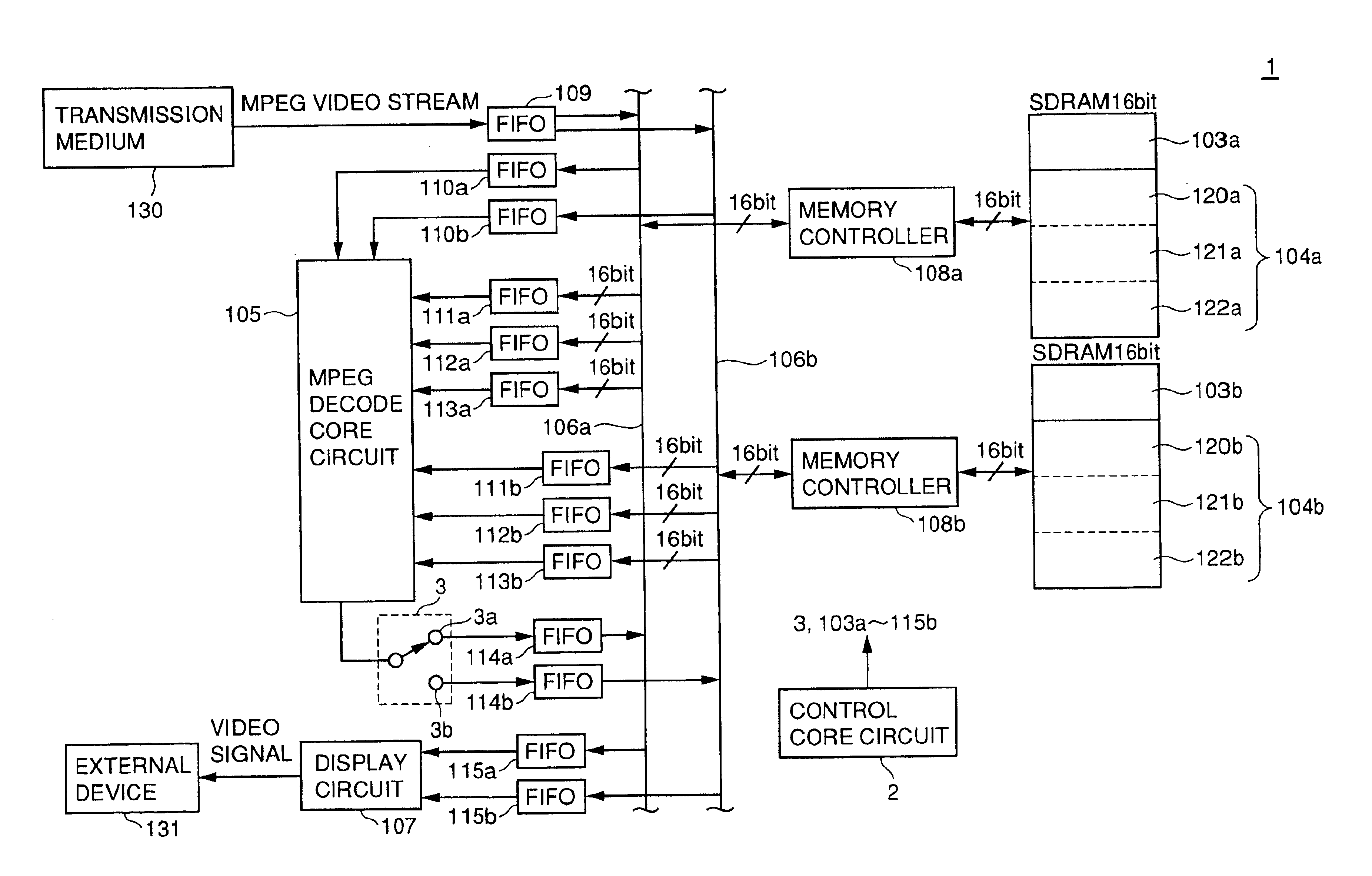
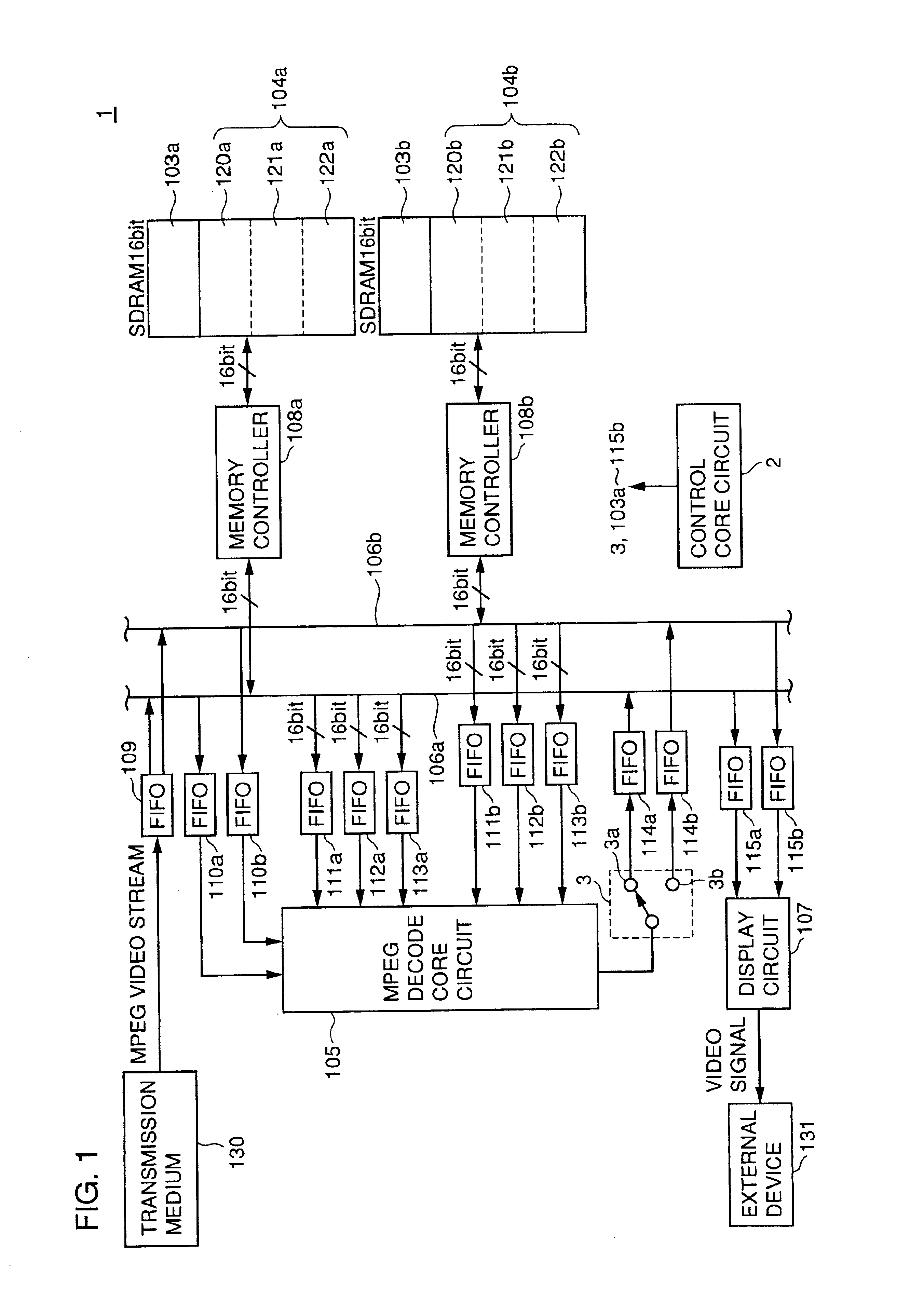
FIG. 1 is a block circuit diagram showing a configuration of an MPEG video decoder 1 of the first embodiment.

MPEG video decoder 1 includes a control core circuit 2, a switch circuit 3, bit buffers 103a and 103b, frame buffers 104a and 104b, an MPEG decode core circuit 105, data buses 106a and 106b, a display circuit 107, memory controllers 108a and 108b, and buffers with FIFO configurations 109, 110a-115b. Circuits 2 and 103a-115b constituting MPEG decoder 1 are mounted on one LSI chip.

Control core circuit 2 controls circuits 3 and 103a-115b.

A video stream transferred from a transmission medium 130 is initially input into buffer 109, and transferred therefrom through e...


PUM


Abstract

An MPEG video decoder 1 decodes a MPEG video stream using a discrete cosine transform together with a motion compensated prediction performing backward prediction and forward prediction. A frame buffer 104a is provided with a storage area for forward-reference luminance data used for the backward prediction and a storage area for rearward-reference color-difference data used for the forward prediction. A frame buffer 104b is provided with a storage area for forward-reference color-difference data used for the backward prediction and a storage area for rearward-reference luminance data used for the forward prediction. Memory access for each of the frame buffers 104a, 104b with an input/output data bus width of 16 bit is performed in a parallel processing.

Description

TECHNICAL FIELDThe present invention relates to a video decoder with an image compression system in accordance with, for example, the MPEG standard,BACKGROUND ARTMultimedia applications handle enormous and various information, and it has been necessary to rapidly process such information for the practical multimedia applications. A data compression / decompression technology is indispensable for rapidly processing the information.One example of such a data compression / decompression technology is an “MPEG (Moving Picture Expert Group)” system. The MPEG system is standardized by an MPEG committee (ISO / IEC JTC1 / SC29 / WG11) affiliated with ISO (International Organization for Standardization) / IEC (International Electro-technical Commission).The MPEG consists of three sections. Part 1, “MPEG systems part,” (ISO / IEC IS 11172 Part 1:Systems) defines multiplex structures and synchronous systems of video data and audio data. Part 2, “MPEG video part” (ISO / IEC IS 11172 Part 2:Video) defines a hig...

Claims


Application Information

Patent Timeline
Patent Type & Authority Patents(United States)
IPC IPC(8): G06T9/00H04N7/36H04N7/26H04N7/50H04N19/423H04N19/433H04N19/50H04N19/503H04N19/51H04N19/577H04N19/61H04N19/625
CPCH04N19/51H04N19/61H04N19/436H04N19/44H04N19/423H04N19/186H04N19/433
Inventor OKADA, SHIGEYUKI
Owner SANYO ELECTRIC CO LTD
Why Eureka
Try Eureka