Mixer circuit

a mixer circuit and mixer technology, applied in the field of mixer circuit improvement, can solve the problems of amplitude error between if-i and ghz band, insufficient image rejection in ghz band, difficult excellent performance in ghz band, etc., and achieve the effect of reducing the phase error of the output and high impedan

Inactive Publication Date: 2005-03-22
NIPPON TELEGRAPH & TELEPHONE CORP
View PDF17 Cites 53 Cited by
  • Summary
  • Abstract
  • Description
  • Claims
  • Application Information

AI Technical Summary

Benefits of technology

A first feature of the present invention is that a source of each of the differential pairs and a differential amplifier is coupled with a power source potential through an impedance circuit which has high impedance for operational frequency of the circuit and short-circuited for D.C. current. This allows to provide a bias potential to a gate of a transistor of a differential pair independently from a bias potential of a gate of a transistor of a differential amplifier. An independent bias potential allows a differential pair and a differential amplifier to have optimized bias potential so that a phase error of an output IF signal is a minimum, in other words, a quadrature component of an output IF signal has the exact phase relation of 90° with an inphase component of an output IF signal.
Another feature

Problems solved by technology

However, a prior art mixer shown in FIG. 6 has a disadvantage in that an image rejection in the GHz band is not enough as a 90° phase shifter with excellent performance in GHz band is difficult.
One of the causes of an IF signal error is an error or a dispersion of mixer circuits.
However, the circuit of FIG. 8 has the disadvantage that amplitude error exi

Method used


Image

  • Mixer circuit
  • Mixer circuit
  • Mixer circuit

Examples


third embodiment

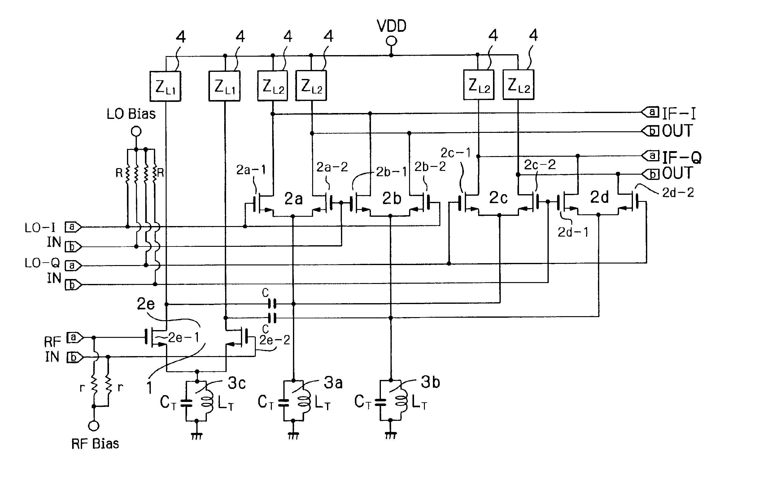
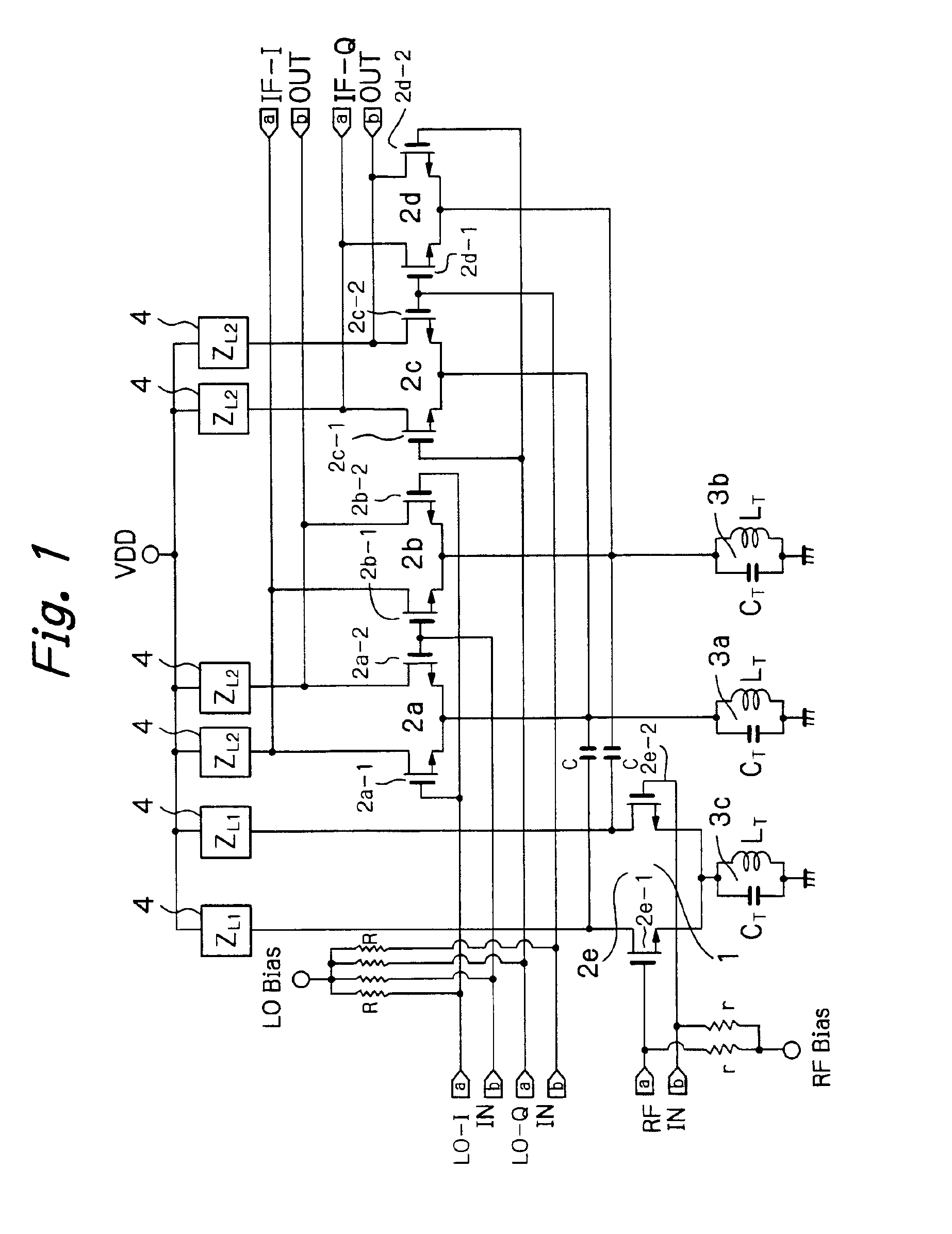
FIG. 4 shows the present invention. FIG. 4 is a complex mixer circuit having a real mixer and an imaginary mixer. A complex mixer circuit has an advantage that a phase error and an amplitude error of an output signal are small.

The FIG. 4 embodiment comprises a pair of quadrature mixers of FIG. 1, and has a feature that a local signal LO and a load impedance are common to both a read mixer and an imaginary mixer. Bias resistors R and r exist in the FIG. 4 embodiment, but are not shown for the sake of simplicity of the figure.

Each of the quadrature mixers in FIG. 4 carries out the multiplication of a pair of RF signals having quadrature relations with each other in balanced form, and a pair of local signals LO having quadrature relations with each other in balanced form. As a load impedance is common, first products are added, and the other products are subtracted, to provide an output IF signal.

A complex mixer circuit has the advantage in that an error component in an output IF signa...


PUM


Abstract

A mixer circuit used in a radio receiver for mixing two frequencies and providing an intermediate frequency which is the difference of the two frequencies. Excellent image rejection is provided by decreasing an amplitude error and a phase error of an output IF signal in differential form.

Description

BACKGROUND OF THE INVENTION1. Field of the InventionThe present invention relates to improvement of a mixer circuit used in a receiver in digital radio communication system, in particular, relates to such a circuit which is excellent in image rejection.2. Description of the Related ArtFIG. 6 shows in general an image rejection mixer circuit, in which a received RF (radio frequency) signal is applied to a pair of multipliers 61 and 62, each of which receives further, a local signal LO, directly or through a 90° phase shifter 63, so that a product of RF and LO is obtained. Then, each multiplier provides a pair of output frequencies FRF+FLO and FRF−FLO, where the former is an undesired frequency and the latter is a desired IF frequency. A product of each of the multipliers is applied to a low pass filter 64, 65, so that a pair of IF signals having a phase difference of 90° are obtained. Then, two IF signals are added in an adder 67 after one of the IF signals is shifted by 90° in a pha...

Claims


Application Information

Patent Timeline
IPC IPC(8): H03D7/00H03D7/16H03D7/14
CPCH03D7/1441H03D7/165H03D7/1458H03D7/1483H03D2200/0043H03D2200/0023H03D2200/0033
Inventor UGAJIN, MAMORUTSUKAHARA, TSUNEO
Owner NIPPON TELEGRAPH & TELEPHONE CORP
Why Eureka
Try Eureka