Pultruded panel

a technology of pultruded panels and pultruded panels, which is applied in the direction of railway bodies, transportation and packaging, window arrangements, etc., can solve the problems of labor and time, significant amounts of raw materials, and the inability to complete the manufacture and assembly of conventional boxcars, so as to improve the temperature regulation, improve the insulation effect, and increase the load carrying capacity

Inactive Publication Date: 2005-03-29
TRINITY IND INC
View PDF33 Cites 64 Cited by
  • Summary
  • Abstract
  • Description
  • Claims
  • Application Information

AI Technical Summary

Benefits of technology

In accordance with teachings of the present invention, several disadvantages and problems associated with insulated boxcars, refrigerated boxcars and other types of temperature controlled railway cars have been substantially reduced or eliminated. For one embodiment a floor assembly for a composite box structure may be formed from pultruded panels. The present invention may include a composite box structure with a temperature control system and an airflow management system satisfactory for use with a refrigerated boxcar or a temperature controlled railway car. A composite box structure formed in part with pultruded panels in accordance with teachings of the present invention provides enhanced insulation, increased load carrying capacity, better temperature regulation, increased service life, and reduced maintenance costs as compared to a typical refrigerated boxcar.

Problems solved by technology

Significant amounts of raw material, labor and time are often required to complete the manufacture and assembly of conventional boxcars.

Method used


Image

  • Pultruded panel
  • Pultruded panel
  • Pultruded panel

Examples


Embodiment Construction

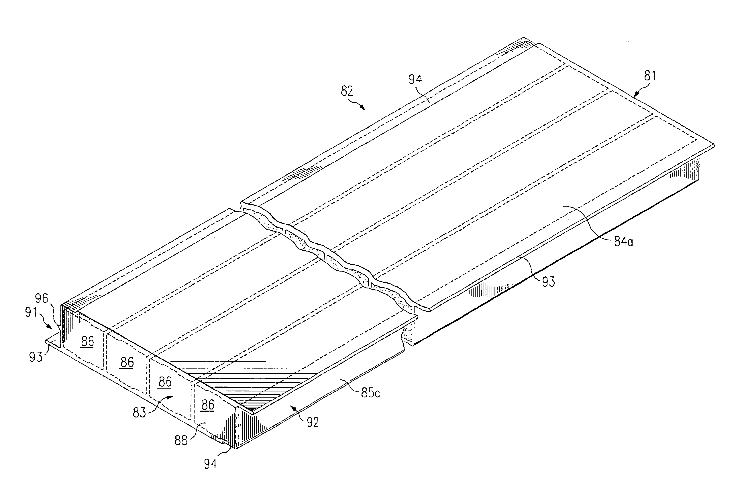
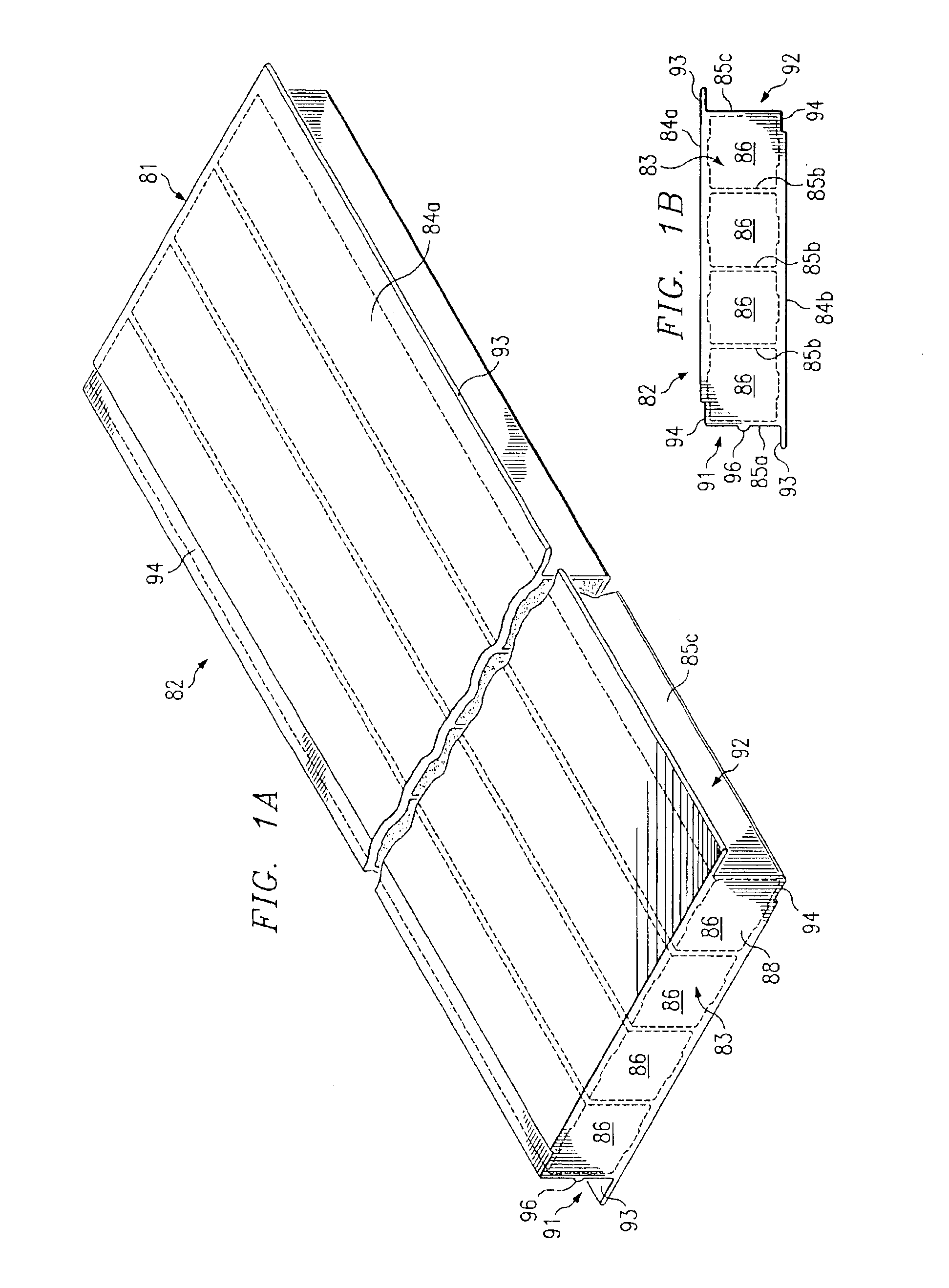
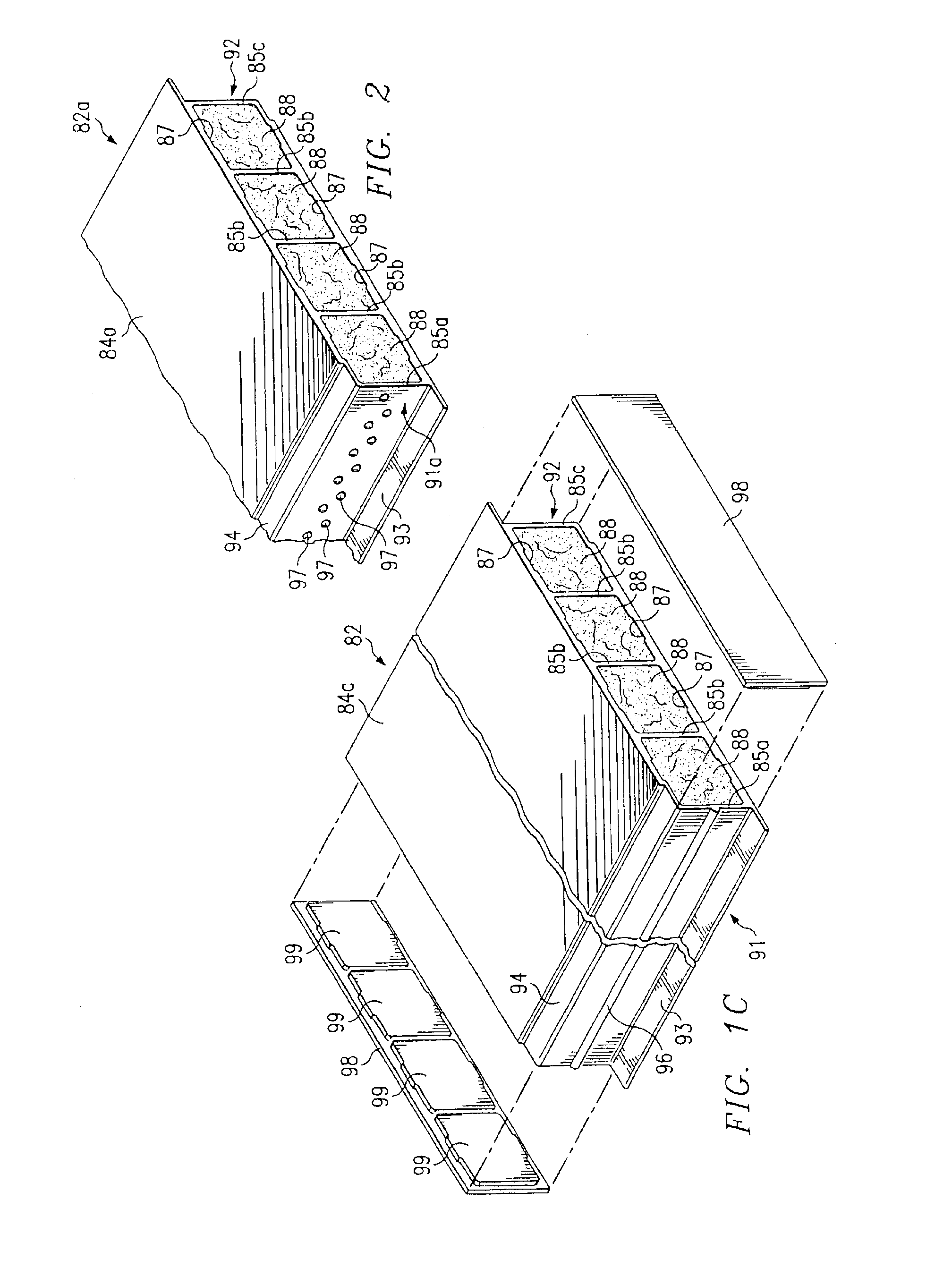
Preferred embodiments of the invention and its advantages are best understood by reference to FIGS. 1A-16 of the drawings, like numerals for like and corresponding parts of the various drawings.

Various aspects of the present invention will be described with respect to forming a floor assembly and interior bulkheads associated with a railway car using pultruded panels. However, the present invention is not limited to panels formed using pultrusion technology (pultruded panels). Panels may be formed in accordance with teachings of the present invention by a wide variety of techniques including injection molding and extrusion technologies. Panels formed in accordance with teachings of the present invention may be satisfactorily used in a wide variety of applications including, but not limited to, commercial buildings, residential building, walkways, bridges, chemical plants, transportation, mass transit and truck trailers (not expressly shown).

U.S. Pat. No. 5,716,487 entitled “Pultrusi...


PUM


Abstract

Pultruded panels having a first longitudinal edge profile and a second longitudinal edge profile may be used to form a floor assembly mounted on a railway car underframe. The pultruded panels may also be used to form walkways, bridges, piers and other structures. A bead may be placed on at least one of the longitudinal edge profiles to form a gap between an adjacent pultruded panel. An adhesive may be placed within the gap to couple or bond adjacent pultruded panels with each other. Void spaces may be formed within the pultruded panel and filled with foam to provide improved resistance to heat transfer through the respective panel. Respective coverings may be placed on opposite ends of each panel to block access to the associated void spaces.

Description

TECHNICAL FIELDThe present invention is related to pultruded panels, which have multiple uses including forming portions of a floor assembly associated with a composite box structure mounted on a railway car underframe.BACKGROUND OF THE INVENTIONOver the years, general purpose railway boxcars have progressed from relatively simple wooden structures mounted on flat cars to more elaborate arrangements including insulated walls and custom designed refrigeration equipment. Various types of insulated boxcars are presently manufactured and used. A typical insulated boxcar includes an enclosed structure mounted on a railway car underframe. The enclosed structure generally includes a floor assembly, a pair of side walls, a pair of end walls and a roof. The side walls, end walls and roof often have an outer shell, one or more layers of insulation and interior paneling.The outer shell of many railway boxcars often has an exterior surface formed from various types of metal such as steel or alu...

Claims


Application Information

Patent Timeline
Patent Type & Authority Patents(United States)
IPC IPC(8): B61D17/04B61D17/12B61D27/00B61D17/10B61D17/00
CPCB61D17/005B61D17/045B61D27/00B61D17/12B61D17/10
Inventor NORTON, ALLEN E.SMITH, STEPHEN W.KNAPP, WILLIAM A.HOOVER, ALEX K.TROUTMAN, DUSTIN L.
Owner TRINITY IND INC
Why Eureka
Try Eureka