Differential sensor apparatus and method for laminated core fault detection

a technology of laminated core and sensor, which is applied in the direction of magnetic property measurement, material magnetic variables, instruments, etc., can solve the problems of eddy currents flowing through shorted laminations and key bars, burning and melting of laminations, and faults in stator cores such as short circuited laminations, so as to reduce the cost of probe manufacturing, improve precision, and simplify the construction of an embodiment of the invention

Inactive Publication Date: 2005-03-29
GENERAL ELECTRIC CO
View PDF10 Cites 27 Cited by
  • Summary
  • Abstract
  • Description
  • Claims
  • Application Information

AI Technical Summary

Benefits of technology

In one example embodiment of the present invention, probe manufacturing costs may be lowered and precision further enhanced by coupling the magnetic flux inducing excitation coils for each yoke in a magnetic series-aiding configuration and coupling the flux sensor coils from each yoke in a magnetic series-bucking arrangement. Construction of an embodiment of the invention may also be simplified and manufacturing cost further reduced by using a single flux-inducing excitation coil that is wound around both yokes of the probe.

Problems solved by technology

Lamination faults in a stator core, such as short circuited laminations, may become highly destructive in large electric machines.
Inter-lamination short circuits (caused by mis-operation or manufacturing defects such as burrs, defects in lamination coating, damage during assembly) cause eddy currents to flow through the shorted laminations and key bars.
The heating caused by these currents can cause burning and melting of the laminations at the location of the defect.
The additional heating can also cause insulation degradation and failure in the stator bars.
Unfortunately, the ring test requires the use of a controllable high-power, high-voltage source and special stator core excitation windings with large cross sections.
Short circuits that are located below the surface of the stator teeth and slots are difficult to find, since thermal diffusion causes the surface temperature rise to become diffuse.
Moreover, because of the high power levels used in the ring test, personnel are not allowed in the bore of the stator core during testing.
In addition, cables used in the test must be appropriately sized to accommodate the high power level which inevitably leads to long setup and removal times. These drawbacks and the high power requirements cause this method to be usually impractical for field test applications.
As in the ring test, a disadvantage of this testing method is that it also requires a special winding for the stator core.
However, when the thickness of a flux-injection type probe exceeds the thickness of about two or three core laminations, sensitivity and selectivity are reduced.
Unfortunately, physical and practical constraints limit the minimum feasible sensor yoke thickness.
Such paint further increases the effective gap between the magnetic yoke and the core which correspondingly reduces the effective sensitivity of the testing probe.
For at least the above reasons, it is very difficult to detect some small faults and, especially, small lamination faults when using known flux-injection probe devices and methods.

Method used


Image

  • Differential sensor apparatus and method for laminated core fault detection
  • Differential sensor apparatus and method for laminated core fault detection
  • Differential sensor apparatus and method for laminated core fault detection

Examples


Embodiment Construction

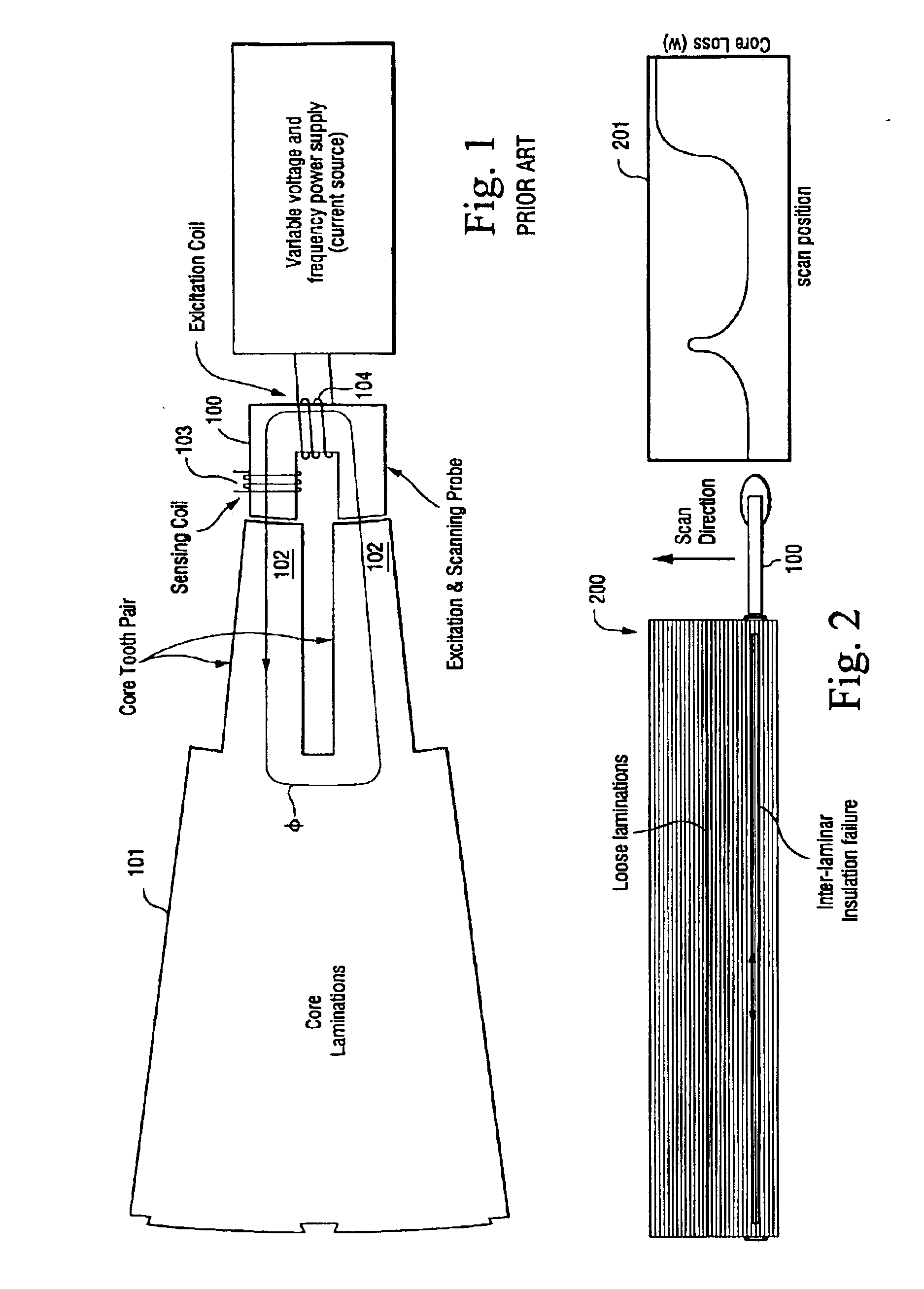
FIG. 1 illustrates the basic flux-injection test concept of the present invention that is used for detecting core lamination faults. An example testing arrangement of the type conventionally used for performing a flux-injection test on the laminated core of an electrical machine is shown. The flux-injection probe consists of a single U-shaped ferromagnetic yoke 100 (which itself may be comprised of laminated sheets) wound with a magnetic flux generating “excitation coil” winding 104. During the testing procedure, the probe is preferably positioned in very close proximity to at least one stator core tooth pair and the excitation coil winding is supplied with an electrical current to inject a magnetic flux (φ) into the stator core laminations. A flux sensing coil (flux sensor) 103 is wound on an arm of the yoke to provide a signal for detecting core lamination faults by calculating a measure of the losses experienced within the core (i.e., core loss). Basically, electromagnetic probe ...


PUM

PropertyMeasurementUnit
thickaaaaaaaaaa
lengthaaaaaaaaaa
lengthaaaaaaaaaa

Abstract

A differential probe is scanned along a stator core tooth portion to detect lamination faults. The probe utilizes two magnetic flux injection yokes arranged side-by-side in relatively close proximity, each yoke having two arm portions and two core-tooth flux-injection surfaces, each yoke being wound with an excitation coil winding and at least one yoke-arm of each yoke having a magnetic flux sensor. Current is supplied to the excitation coil windings on each yoke to inject magnetic flux into the stator core laminations while the probe is moved in a scanning process along the core teeth across the laminations. The magnetic flux differential detected at adjacent regions in the core by flux sensors on each of the two yokes is used to incrementally evaluate the core for laminations faults. The output produced by the differential probe may be converted to a digital signal and provided to a computer system for storage and future analysis.

Description

BACKGROUND OF INVENTIONThe present invention relates generally to testing devices and methods and, more particularly, to a testing method and apparatus for detecting and locating faults in laminated cores of electric machines.For the purposes of the following discussion, a lamination segment of the stator of a large generator may be considered as an example structure on which the present method and apparatus is suited for performing lamination fault testing. A conventional laminated core segment of a large generator stator includes a back iron portion, teeth and slots. Lamination segments are typically formed into a magnetic core by stacking. A plurality of lamination segments (eighteen lamination segments each being twenty degrees, as one example) may be used to form a complete first lamination layer with the next plurality of lamination segments forming a complete second lamination layer on top of and offset from the lamination segments in the first lamination layer. Such stacking...

Claims


Application Information

Patent Timeline
Patent Type & Authority Patents(United States)
IPC IPC(8): G01N27/82
CPCG01R31/34G01N27/82
Inventor KLIMAN, GERALD BURTSHAH, MANOJ RAMPRASADLEE, SANG-BIN
Owner GENERAL ELECTRIC CO
Why Eureka
Try Eureka