An object of the present invention is to specify a method for determining a helical groove structure in the surface of a finely finished cylindrical workpiece which permits qualitatively and quantitatively reliable statements on the formation and degree of salience of the helical groove structure. The aim in this case is to lend prominence to the speed of the method, the cost-effective implementation and the simple handling of the device.
The use of a fast
image processing algorithm permits a substantially quicker detection and quantification of helical grooves than is possible in the case of a sampling
system. The use of
image series renders the calculation of
helix angles independent of adjustment, and thereby facilitates the handling of the measuring
system used. A further
advantage is to be seen in that standard components can be used to carry out the method according to the present invention. This ensures a cost-effective implementation when constructing the measuring
system.
It is possible to proceed in the following way when carrying out the present invention specifically when a
single image suffices for detecting the
surface structure:a) The camera, and the workpiece are mutually aligned by adjusting the camera and the workpiece at a defined angle relative to one another. A
high contrast is generated between
flute peaks and troughs with the aid of illumination which is incident in a very flat fashion. The image section should be chosen such that between 5 and 50 flutes are to be seen. Fewer flutes limit the statistical reliability and reproducibility of the result, while more reduce the achievable resolution.b) An image of the surface characteristics of the workpiece is recorded. Enlarged grey-scale images of the
grinding texture can be recorded, for example, via a macrolens and a
CCD camera. It suffices to
record a
single image of the surface for
helix angles in the range of degrees.c) A
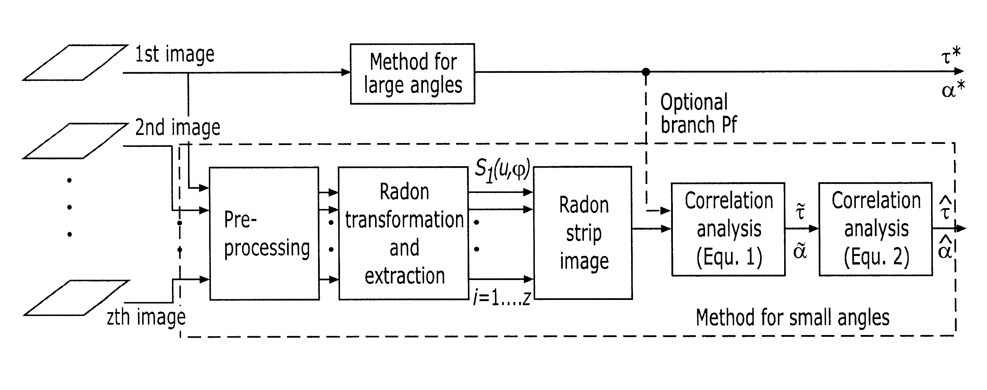
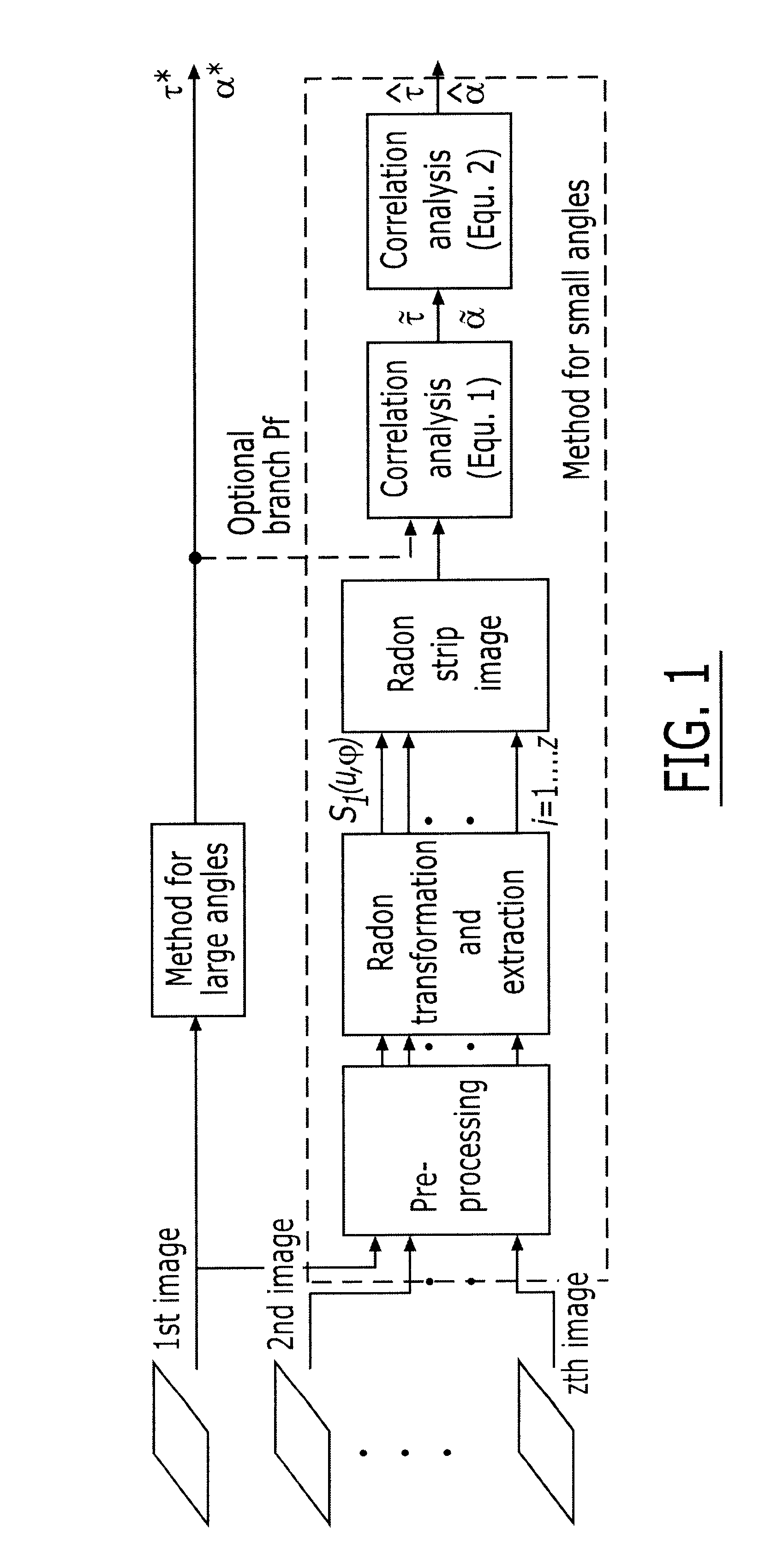
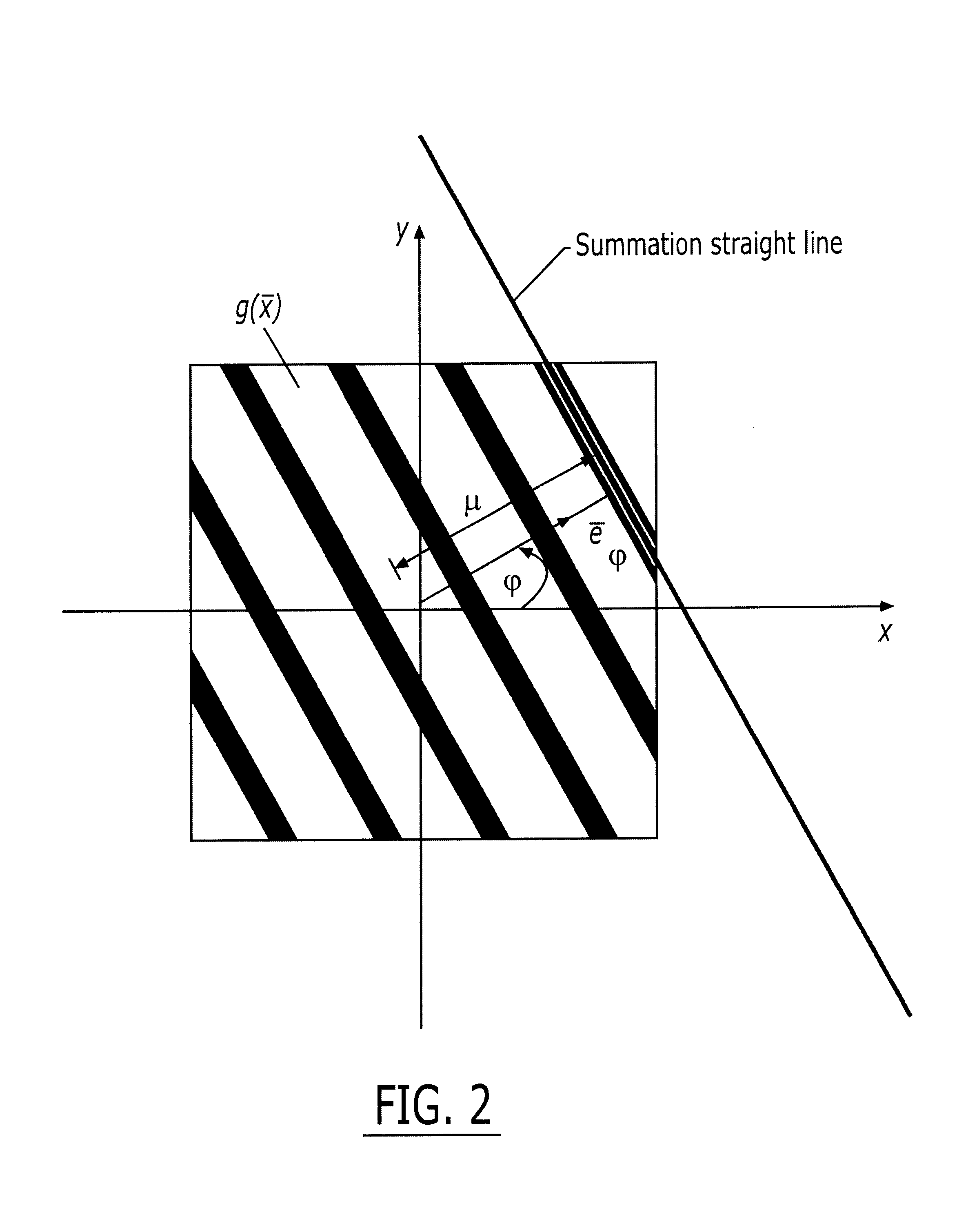
Radon transformation of the image is carried out. The
Radon transformation is a method which effectively visualizes linear structures in images—The angular position of the flutes in the image is determined with the aid of the
Radon transform of the image. The angle obtained from the
Radon transform is, however, not yet the desired
helix angle.d) The
helix angle is determined from the
Radon transform. The difference between the angle defined in step a) and the angle determined in step c) is the desired
helix angle. This method is particularly suitable for large helix angles in the range of degrees.
It is possible to proceed in the following way in an expedient refinement of the method according to the present invention, this mode of procedure being indicated when a plurality of images are required for the data-reliable detection of the
surface structure:a) The workpiece is set rotating. Theoretically, it is also possible to set the camera rotating around the workpiece, but it is simpler to set the workpiece rotating. This can be performed, for example, with the aid of a suitable drive by means of appropriately mounting the workpiece.b) A plurality of images of the surface characteristics of the workpiece are recorded at a constant twisting angle. For relatively small helix angles of the magnitude of a few minutes, it is not sufficient to process only one image. In order to be able to measure small helix angles with a higher accuracy, plurality of images of the surface are recorded, affected by helical grooves, at a defined twisting angle (that is to say, a fixed image spacing in the circumferential direction).c) The Radon transformation to be carried out is carried out for each image and a so-called Radon strip is extracted in each case therefrom. The periodic
power component is calculated as the ratio of the proportion of the
machining marks to the surface under consideration. Each
flute is projected, by means of a Radon transformation carried out for each image, onto a region about local maximum, to be precise all parallel flutes of an image are projected,onto a strip via a
fixed angle. The flutes appear in the image at the
fixed angle with different spacings from the origin.d) The Radon strips of the Radon transforms of each image are juxtaposed in a so-called Radon strip image. The region (Radon strip) of interest of each transform is extracted, and these Radon strips are assembled in an image. The
helix angle is present enlarged in the Radon strip image thus produced, and can therefore be measured more accurately.e) A
correlation analysis of the juxtaposed Radon strips is carried out. The helix angle can be determined very reliably, accurately and independently of adjustment owing to the correlation of the Radon strips.

