High-speed switching circuit and automotive accessory controller using same

a high-speed switching circuit and controller technology, applied in the direction of emergency protective circuit arrangement, electric vehicles, electric devices, etc., can solve the problems of not being able to detect and respond to rapid current changes using control circuits with conventional shunt resistors, and the problem described above becomes particularly acute, and achieves the effect of higher shunt resistor values

Inactive Publication Date: 2005-04-05
YAZAKI NORTH AMERICA
View PDF7 Cites 19 Cited by
  • Summary
  • Abstract
  • Description
  • Claims
  • Application Information

AI Technical Summary

Benefits of technology

As hereinafter described, higher shunt resistor values can be achieved by extending the overlying traces across a single layer of insulative board, by increasing the number of trace layers, or by a combination of these techniques.

Problems solved by technology

A problem arises where it is essential to detect and respond to current changes very quickly.
Therefore, it may be impossible to detect and respond to rapid current changes using control circuits with conventional shunt resistors.
The problem described above becomes especially acute if pulse width modulation is used to control the magnitude of the load current.

Method used


Image

  • High-speed switching circuit and automotive accessory controller using same
  • High-speed switching circuit and automotive accessory controller using same
  • High-speed switching circuit and automotive accessory controller using same

Examples


Embodiment Construction

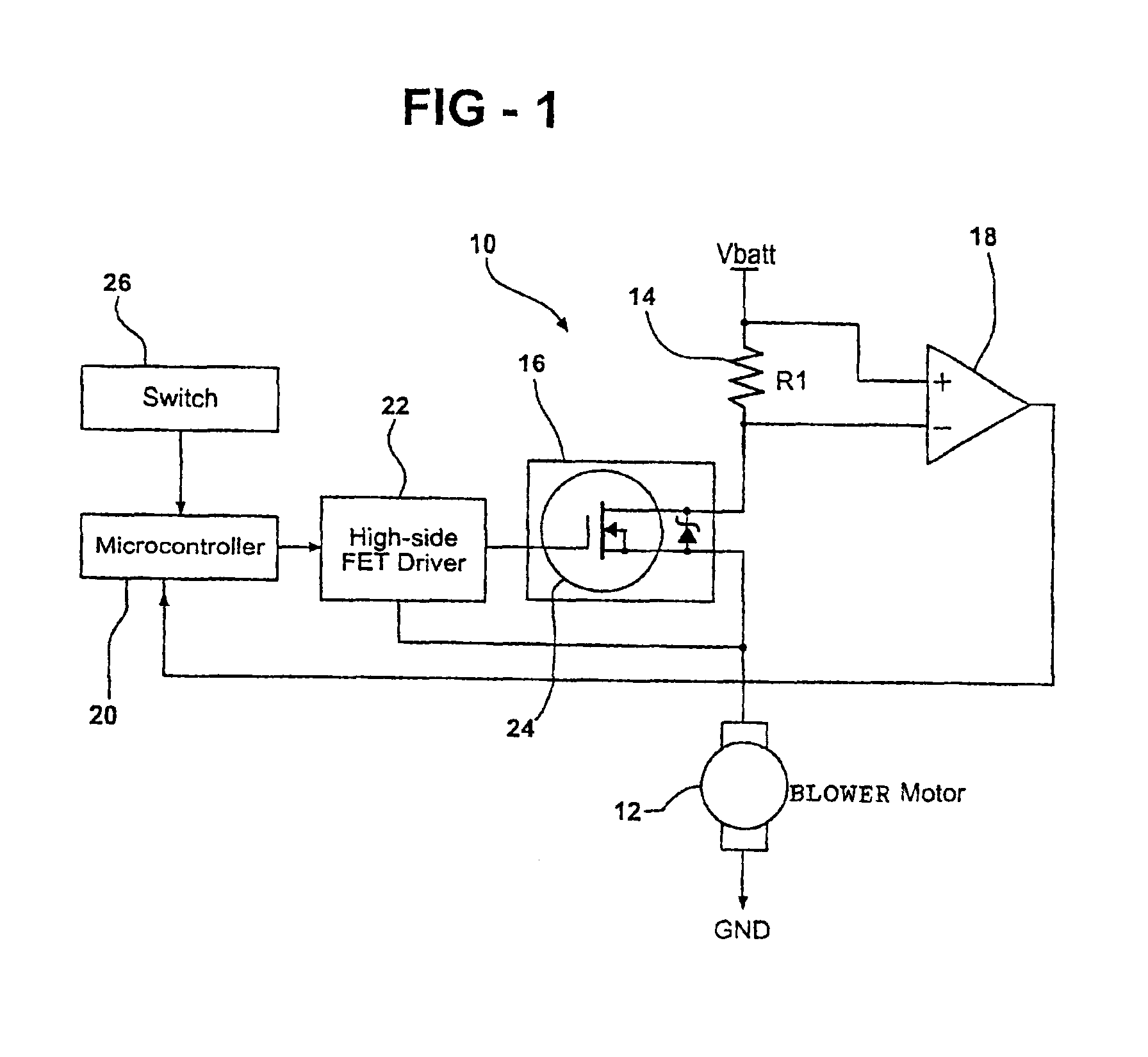
FIG. 1 shows a control circuit 10 for an automotive accessory load circuit which, in this case, includes a blower motor 12. The blower motor 12 is connected in series with a shunt resistor 14 and an FET switch 16 operating in a pulse width modulation (PWM) mode to supply current to motor 12 from a dc supply labeled battery Vbatt.

The opposite terminal ends of the shunt resistor 14 are connected as opposite polarity inputs to a detector circuit 18 such as a comparator or operational amplifier. The output of the detector 18 goes high if the measured voltage across the shunt resistor 14 exceeds a predetermined threshold value associated with, for example, high motor current due to an intake obstacle, overload or short circuit of the blower motor.

The detector output is connected as a data input to a micro-controller 20 which, in turn, controls a high side PET driver circuit 22. The output of the driver circuit is connected to the switching terminal of an FET 24 in circuit 16.

Microcontrol...


PUM


Abstract

A high-speed switching circuit with a low or zero inductance shunt resistor is constructed using a trace resistor having parallel overlying trace portions on opposite plane faces of a printed circuit board. The resulting shunt resistor is used in combination with a detector to input data to a microcontroller which controls an automotive load device such as a blower motor. The traces which form the resistor may be extended by horizontal or vertical zig-zag folding or a combination of the two.

Description

FIELD OF THE INVENTIONThis invention relates to switching circuits and more particularly to a switching circuit using a shunt resistor for current sensing made up of overlying, opposite-direction traces on opposite sides of a printed circuit board such that the shunt resistor is essentially inductance free. The invention is advantageously applied to an automotive accessory control circuit using pulse width modulation (PWM).BACKGROUND OF THE INVENTIONIt is known to use low ohmage shunt resistors to measure current through a load. The resistor is connected in series with the load such that the voltage across the resistor represents load current. This voltage can be used as an input to a detector circuit to determine when measured current rises above or falls below some decision point value.A problem arises where it is essential to detect and respond to current changes very quickly. Resistors of traditional construction have both body and lead inductance, a characteristic which generat...

Claims


Application Information

Patent Timeline
Patent Type & Authority Patents(United States)
IPC IPC(8): G01R1/20G01R1/00H02H1/00H02H3/087H05K1/16
CPCH05K1/167G01R1/203H02H1/0007H05K2201/09672H05K2201/09263H02H3/087
Inventor GUO, SAM Y.
Owner YAZAKI NORTH AMERICA
Why Eureka
Try Eureka