Color component aperture stops in projection display system

a technology of projection display and color component, applied in the field of electronic projector optical systems, can solve the problems of reducing increasing costs, and reducing the range of operating temperatures, so as to reduce the contrast of reflective electronic projection displays and increase costs. , the effect of limiting contras

Inactive Publication Date: 2005-04-12
RGT UNIV OF MINNESOTA
View PDF21 Cites 52 Cited by
  • Summary
  • Abstract
  • Description
  • Claims
  • Application Information

AI Technical Summary

Benefits of technology

However, contrast in these known systems is limited due to use of MacNeille prisms as the polarization beam splitters (PBSs) in different arrangements. A MacNeille prism PBS has limited contrast due to skew-ray depolarization effects, as described in U.S. Pat. No. 5,327,270. The depolarized light reduces the contrast of reflective electronic projection displays, and particularly those employing liquid crystal-on-silicon (LCOS) light valves. As described in the '270 patent, compensation for the skew-ray depolarization requires an additional quarter-wave plate, which increases cost, requires precision alignment and restricts the range of operating temperatures.
Generally, reflective liquid crystal on silicon (LCOS) li...

Problems solved by technology

However, contrast in these known systems is limited due to use of MacNeille prisms as the polarization beam splitters (PBSs) in different arrangements.
As described in the '270 patent, compensation for the skew-ray depolarization requires an additional quarter-wave plate, which increases cost, requires precision alignment and restricts the range of operating temperatures.
In addition to reduced contrast, increased NA re...

Method used


Image

  • Color component aperture stops in projection display system
  • Color component aperture stops in projection display system
  • Color component aperture stops in projection display system

Examples


Embodiment Construction

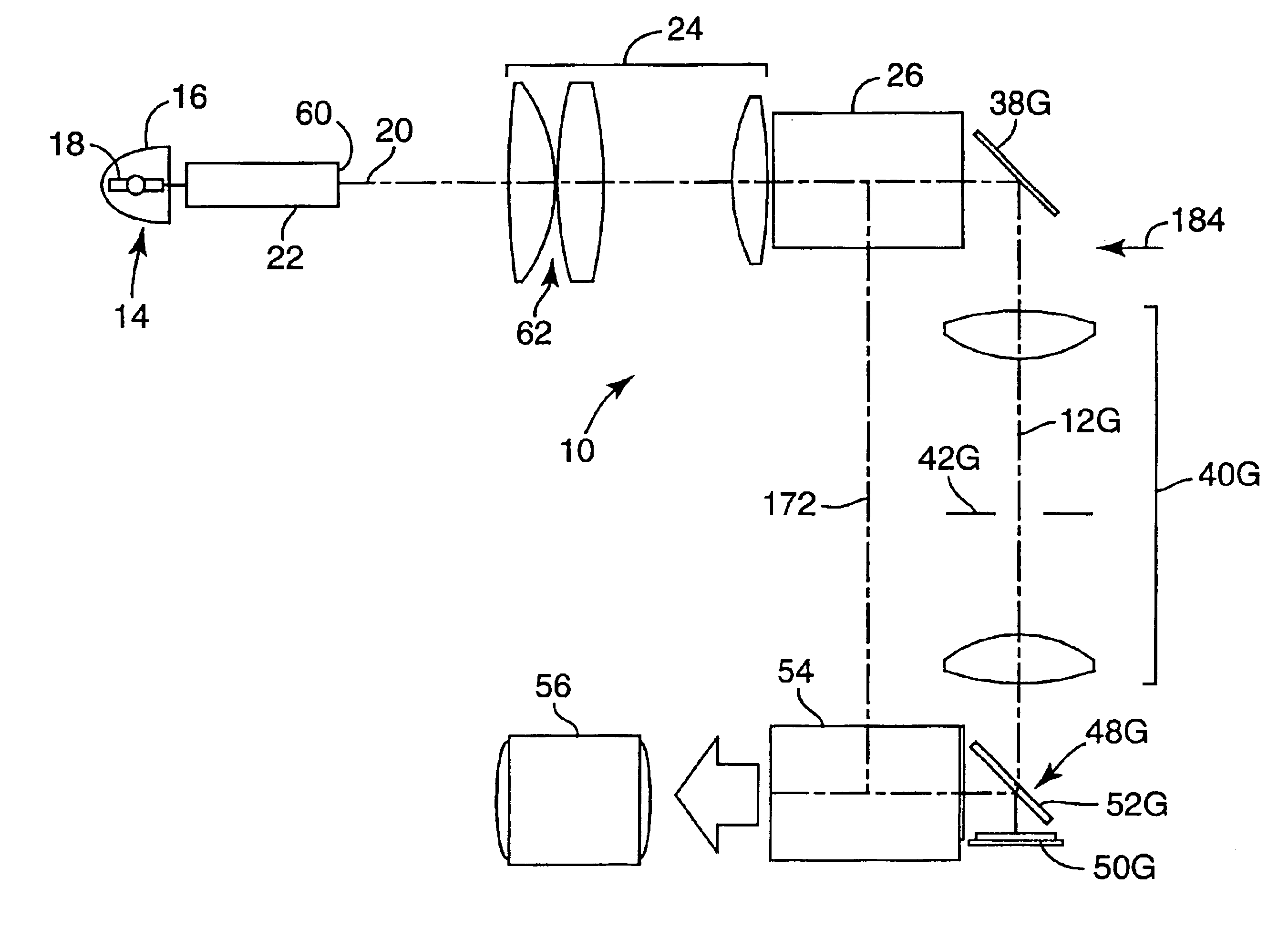
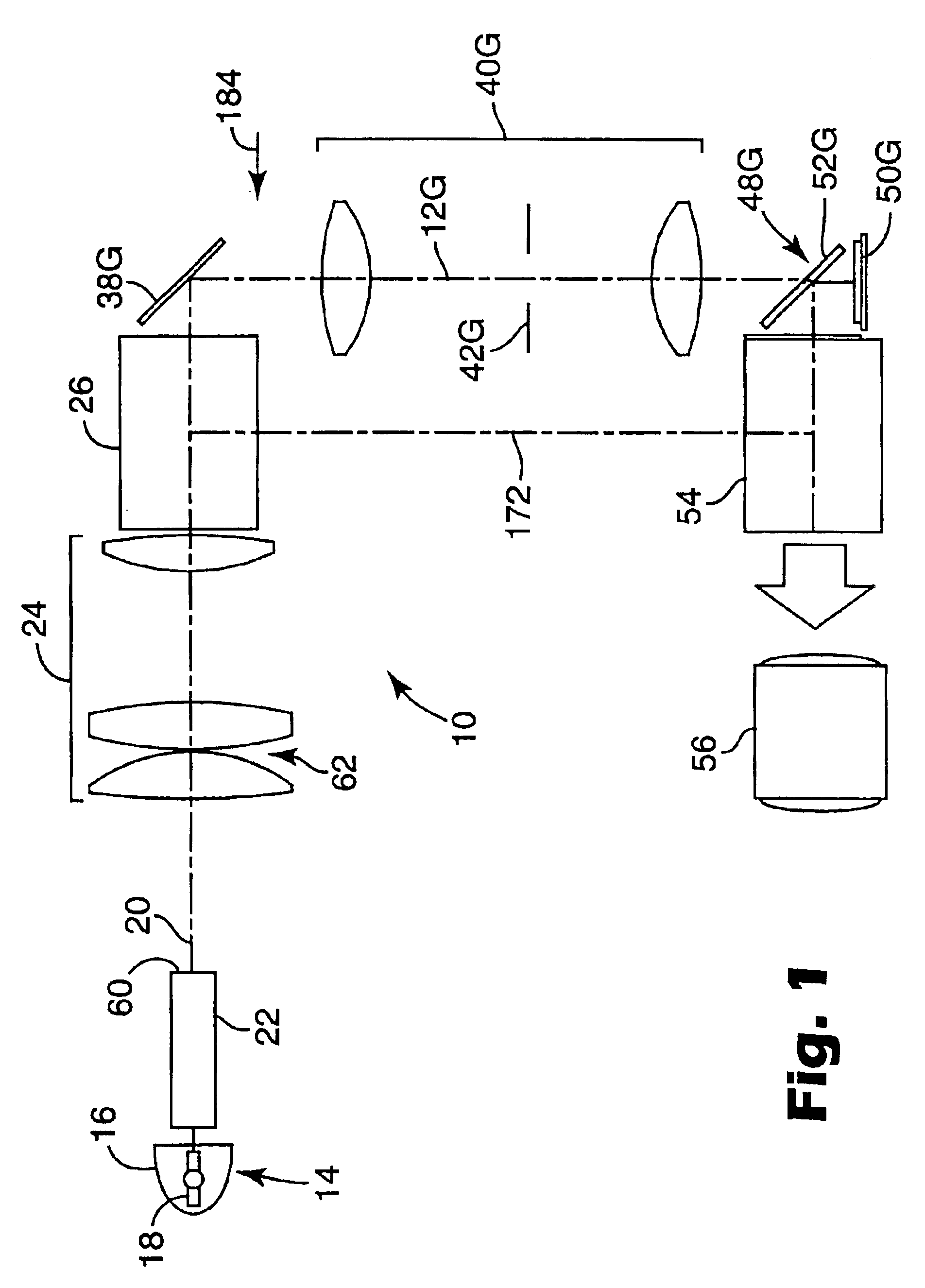
FIG. 1 is a diagram of an embodiment of a reflective projection display system 10 illustrating an example of an operating environment for the present invention. Projection display system 10 (sometimes referred to herein as projector 10) includes three color component optical paths 12 (only one shown) that correspond to the respective primary color light components red, green and blue. For purposes of clarity, FIG. 1 shows only one of the color component optical paths, which is designated color component optical path 12G to correspond to the green primary color component.

It will be appreciated that the red and blue color component optical paths will be the same as, but in places offset from, green color component optical path 12G. Elements of projector 10 that are specific to one primary color light component will be indicated by a corresponding alphabetic suffix (i.e., “R,”“G,” or “B”). Elements of projector 10 that are not specific to one primary color light component will not incl...


PUM


Abstract

A projection display system employs one or more color modifying aperture stops, such as apodizing aperture stops, to provide high contrast, balanced color and high throughput. One projection system includes a reflective liquid crystal-on-silicon light valve positioned with a polarizing beam splitter, such as a wire grid polarizing beam splitter, for each of the primary color component light paths to separately impart image information into each of the primary color components of light. A color combiner receives and combines the primary color components of light with imparted image information to provide light representing a polychromatic display image. At least one aperture stop is positioned along at least one of the primary color component light paths to balance relative intensities of the primary color components of light.

Description

TECHNICAL FIELDThe present invention relates to electronic projector optical systems and, in particular, to employing shaped aperture stops to improve color balance and image contrast.BACKGROUND AND SUMMARY OF THE INVENTIONVarious arrangements of optical layouts are known for projection system with reflective liquid crystal displays. Examples are described in U.S. Pat. Nos. 6,309,071 and 6,113,239 and in High Contrast Color Splitting Architecture Using Color Polarization Filters, Michael G. Robinson et al, SID 00 Digest, p. 92-95. One optical layout described in the Robinson et al. article employs proprietary polarization filter technology (i.e., ColorSelect™ polarization filter technology), available from ColorLink, Inc. of Boulder, Colo., USA, to achieve a reported contrast of more than 500:1.However, contrast in these known systems is limited due to use of MacNeille prisms as the polarization beam splitters (PBSs) in different arrangements. A MacNeille prism PBS has limited contr...

Claims


Application Information

Patent Timeline
IPC IPC(8): H04N9/31G03B21/00
CPCG02B5/005G02B27/1026G02B27/1046G02B27/145G03B21/2073G02B27/58H04N9/3105H04N9/3167H04N9/3197G02B27/149H04N9/31G03B21/00
Inventor ENGLISH, JR., R. EDWARDDONNELLY, SEAN M.MAGARILL, SIMONCONNOR, ARLIE RICHARD
Owner RGT UNIV OF MINNESOTA
Why Eureka
Try Eureka