Power transmission control device for vehicle

a technology for power transmission and control device, which is applied in electrical control, gearing, hoisting equipment, etc., can solve the problems of not being able to control the remaining capacity of a battery, affecting the drivability of the vehicle, and not smooth switching between a speed increasing mode and a constant speed mode. , to achieve the effect of improving fuel consumption

Inactive Publication Date: 2005-04-12
MITSUBISHI ELECTRIC CORP
View PDF12 Cites 39 Cited by
  • Summary
  • Abstract
  • Description
  • Claims
  • Application Information

AI Technical Summary

Benefits of technology

As a result, in the same manner as claim 1, when it is necessary to supply an electric power to a large-capacity load or to rapidly charge the battery falling in an over-discharge state within a range of low speed of the internal combustion engine after the starting thereof, it is possible to generate an electric power of a high output by operating the electric rotating machine at an increasing speed, thereby enabling to meet a large-capacity load with a relatively small-sized electric rotating machine. To achieve this high-output power generation, it is no more necessary to have any increase in engine speed of the internal combustion engine, eventually resulting in improvement in fuel consumption.

Problems solved by technology

Since the conventional auxiliary machine drive is constituted as described above, a problem exits in that switching between a speed increasing mode and a constant speed mode is not smooth.
As a result, a problem in vehicle drivability comes out.
Therefore, in the case of controlling the charging generator for increasing speed, another problem exists in that conditions of electrical loads or a remaining capacity of a battery is not involved.
A further problem exists in that switching cannot be carried out under optimum conditions utilizing various signal data such as cooling water temperature of the internal combustion engine, vehicle velocity, and shift position location.

Method used


Image

  • Power transmission control device for vehicle
  • Power transmission control device for vehicle
  • Power transmission control device for vehicle

Examples


embodiment 1

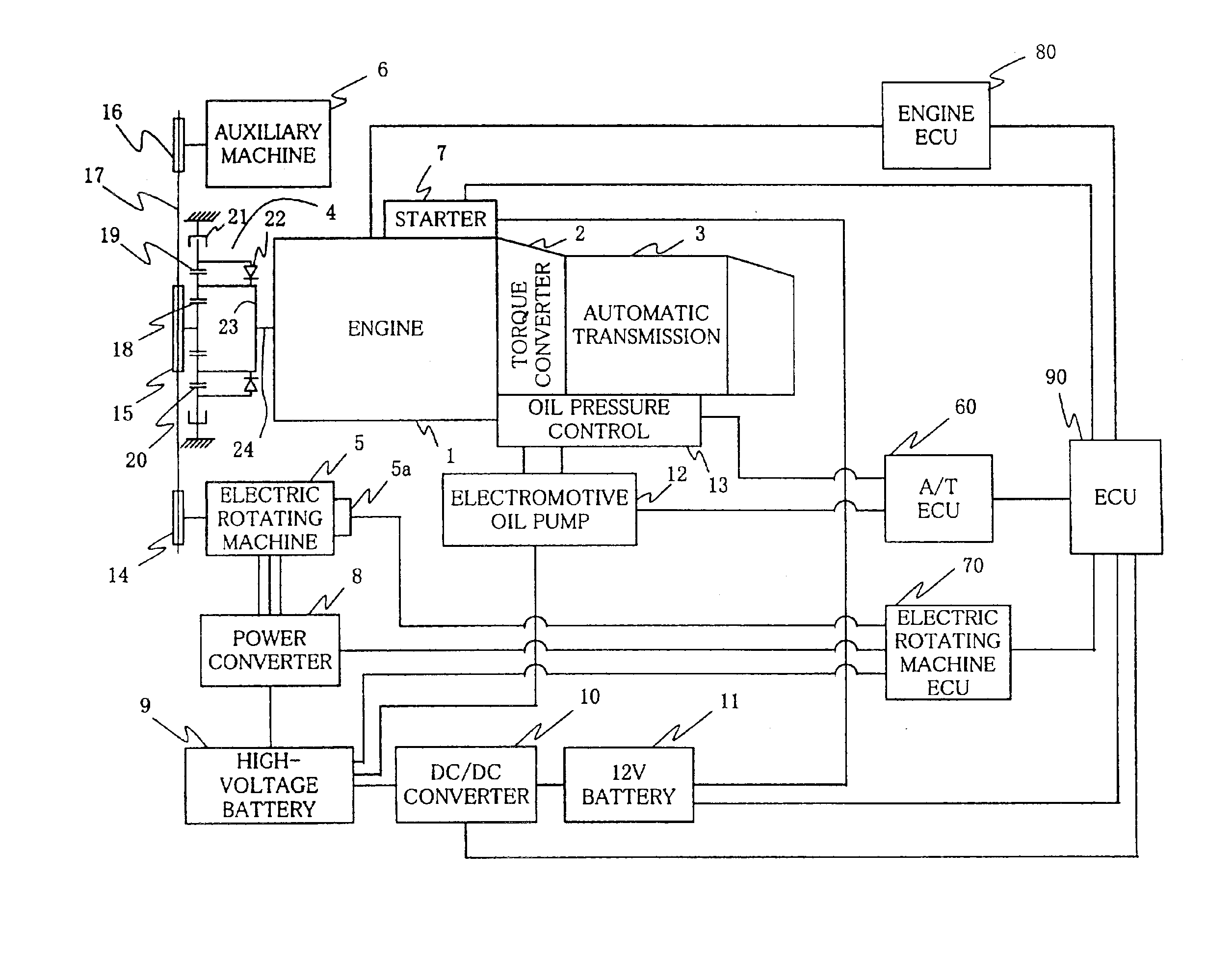
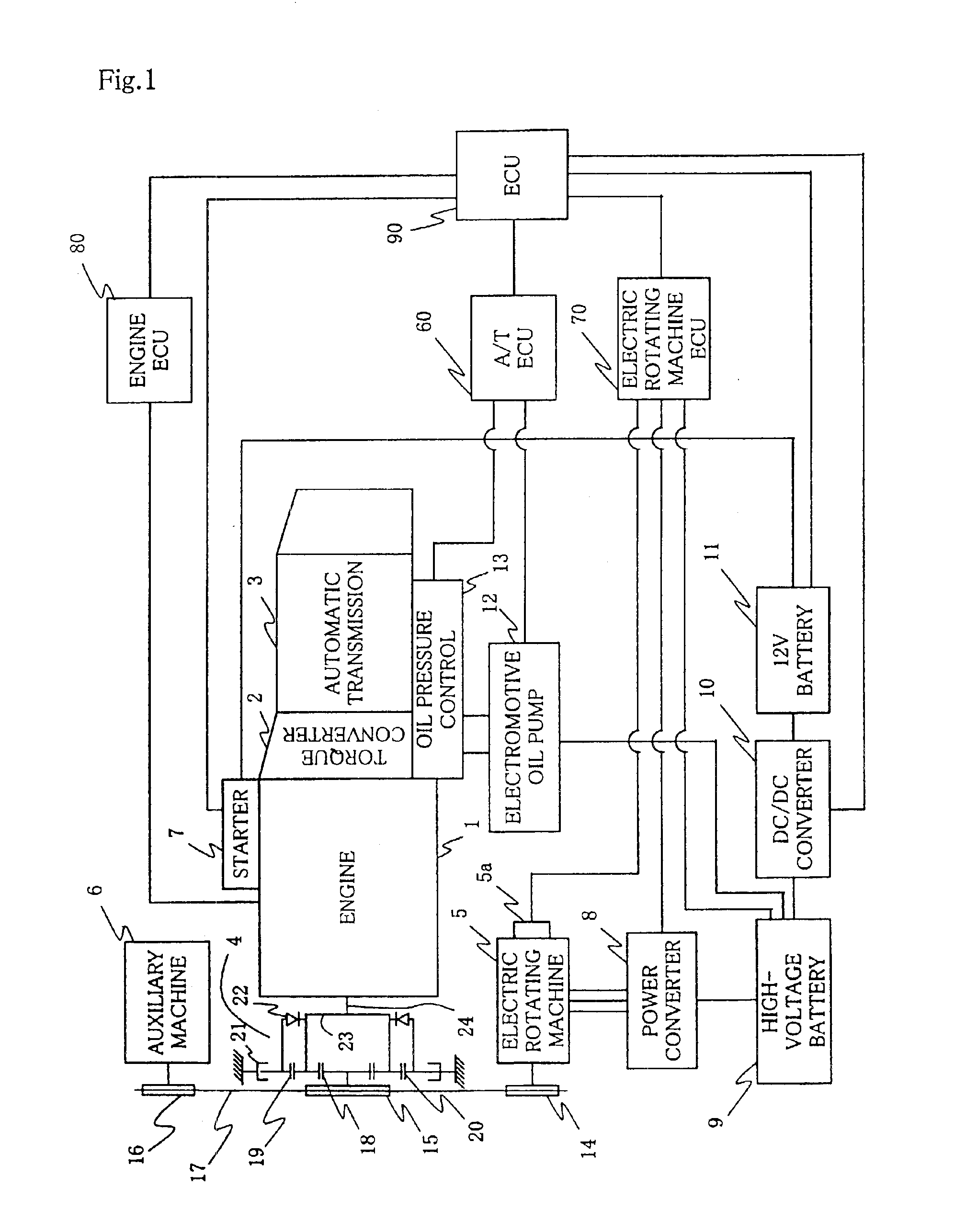
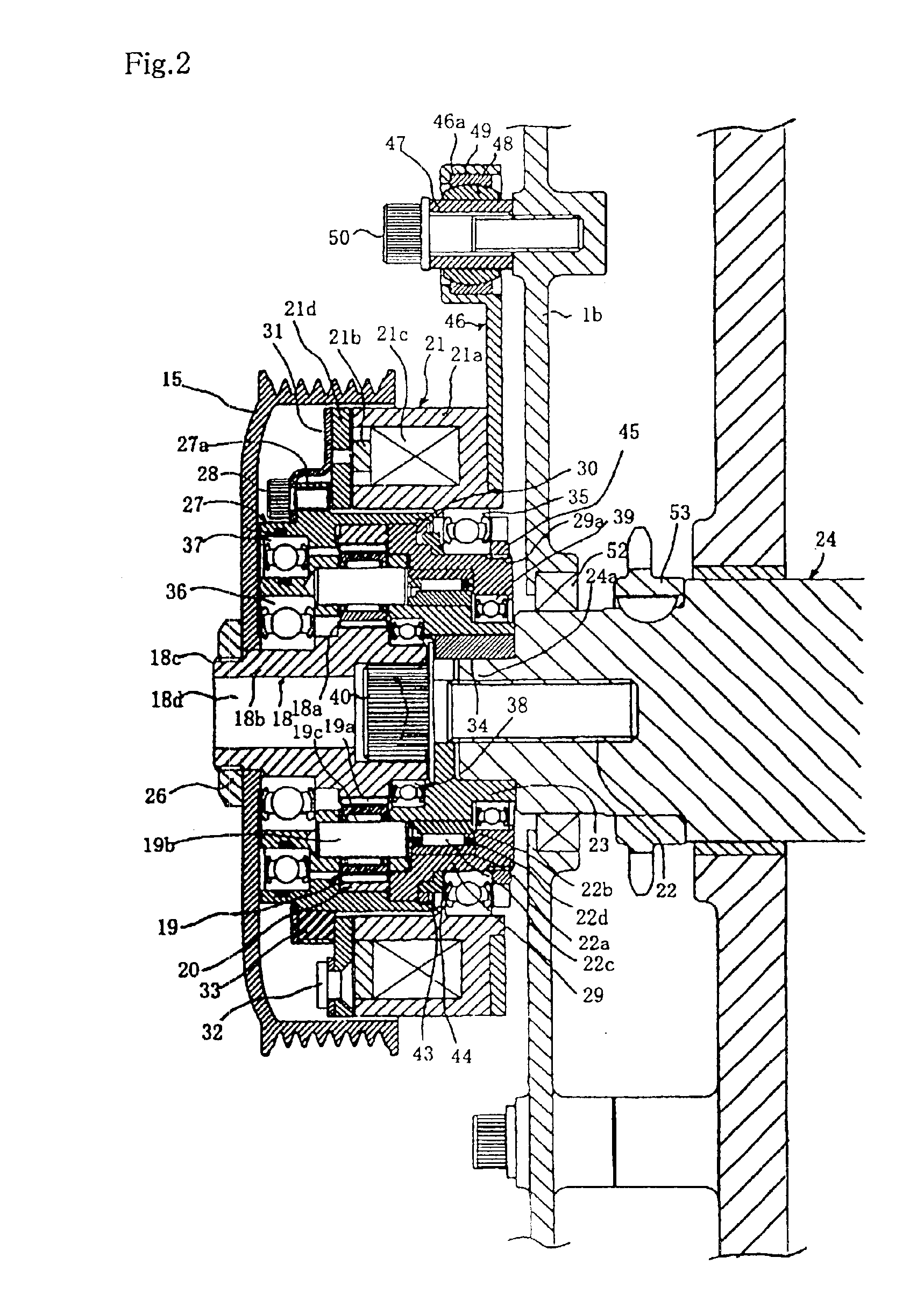
FIGS. 1 through 5 are to explain constitution and operation of a power transmission control device for vehicle according to a first preferred embodiment of the present invention. FIG. 1 is a block diagram of a system including a vehicle power transmission apparatus and a control device thereof. FIG. 2 is a cross sectional view showing a specific example of a constitution of the vehicle power transmission apparatus. FIGS. 3 and 4 are time charts for explaining operation. FIG. 5 is a characteristic chart for explaining a power generation mode of a generator.

Referring now to a system block diagram of FIG. 1, reference numeral 1 designates an internal combustion engine, and this internal combustion engine 1 comprises a torque converter 2 equipped with a lockup mechanism mounted and an automatic transmission 3 (hereinafter referred to as A / T). Further, the internal combustion engine 1 is provided with a power transmission 4, an electric rotating machine 5 functioning as an electric motor...


PUM


Abstract

A power transmission control device for vehicle controls switching between a speed increasing mode and a constant speed mode on the basis of electrical load, battery or the like, and shock due to switching is less. The power transmission control device includes: an electric rotating machine 5; a crank pulley 15; a planetary gear mechanism consisting of a sun gear 18, a planetary gear 19 and an internal gear 20; and controller 70 for controlling an electromagnetic clutch 21. The electromagnetic clutch 21 is ON to operate the planetary gear mechanism as a speed increasing mechanism and drive the electric rotating machine 5 at an increasing speed, when engine speed of the internal combustion engine 1 is not higher than a predetermined value, remaining capacity of the battery 9 is not more than a predetermined level or electrical load is in a high-load state.

Description

BACKGROUND OF THE INVENTION1. Field of the InventionThe present invention relates to a power transmission control device for vehicle capable of controlling a change gear ratio when an internal combustion engine is started with an electric rotating machine acting as a start-up motor and when the electric rotating machine acting as an alternator or auxiliary machines are driven from the internal combustion engine.2. Description of the Related ArtAuxiliary machines such as compressor or oil pump, charging generator (alternator) and the like are mounted on a vehicle driven by an internal combustion engine and the internal combustion engine drives these auxiliary machines. FIG. 6 shows a prior art of a drive of these auxiliary machines, and is a cross sectional view showing a technique disclosed in the Japanese Patent Publication (examined) No. 58069 / 1994.This auxiliary machine drive includes a disk-shaped carrier 102 accommodated in an internal part of a housing 101, and an input shaft ...

Claims


Application Information

Patent Timeline
Patent Type & Authority Patents(United States)
IPC IPC(8): F02N15/02F02N15/04F16H55/49F16H55/36F16H3/54F16H3/44F02B67/06F02D29/06F02D45/00F02N11/04F16D27/02H02P9/04
CPCF02B67/06F02N15/046Y10T477/26F16H55/49F16H3/54
Inventor KITAMURA, YUTAKAODAHARA, KAZUHIROSHIROYAMA, SHIGERU
Owner MITSUBISHI ELECTRIC CORP
Why Eureka
Try Eureka