High strength steel pipe for an air bag and a process for its manufacture

a technology of steel pipe and air bag, which is applied in the direction of furniture, heat treatment equipment, pedestrian/occupant safety arrangements, etc., can solve the problems that the technology disclosed in the above-mentioned patent publications is not necessarily adequate, and achieve excellent workability and weldability, high strength, and high dimensional accuracy

Inactive Publication Date: 2005-04-12
NIPPON STEEL CORP
View PDF8 Cites 25 Cited by
  • Summary
  • Abstract
  • Description
  • Claims
  • Application Information

AI Technical Summary

Benefits of technology

This invention was made in light of the above-described present circumstances, and its object is to provide a high strength steel pipe for air bags which has high dimensional accuracy and excellent workability and weldability and which has a high strength and particularly a high tensile strength of 900 MPa or higher and excellent resistance to bursting and excellent low temperature toughness, and which can adequately cope with an increase in the pressure of gas blown into air bags and a decrease in the thickness of steel pipes, a manufacturing process therefor, and an accumulator for an air bag.
As a result, particularly with respect to the effect of a texture of a steel on low temperature brittleness, it was found that anisotropy has a greater effect than does the constitution of a texture, and that the anisotropy of a certain (crystal) plane orientation in the texture has an intimate relationship to improving low temperature brittleness.

Problems solved by technology

In the past, air bag systems were of the type employing explosive chemicals, but they are expensive, and due to environmental problems and recycling problems, in recent years, a type has been developed using an accumulator made of a steel pipe filled with argon gas or the like, and this type is increasingly used.
Therefore, it is thought that as the pressure of the gas blown into air bags increases and as the wall thickness of steel pipes decreases, there may be cases in which the technologies disclosed in the above-mentioned patent publications are not necessarily adequate from the standpoint of resistance to bursting.

Method used


Image

  • High strength steel pipe for an air bag and a process for its manufacture
  • High strength steel pipe for an air bag and a process for its manufacture
  • High strength steel pipe for an air bag and a process for its manufacture

Examples


examples

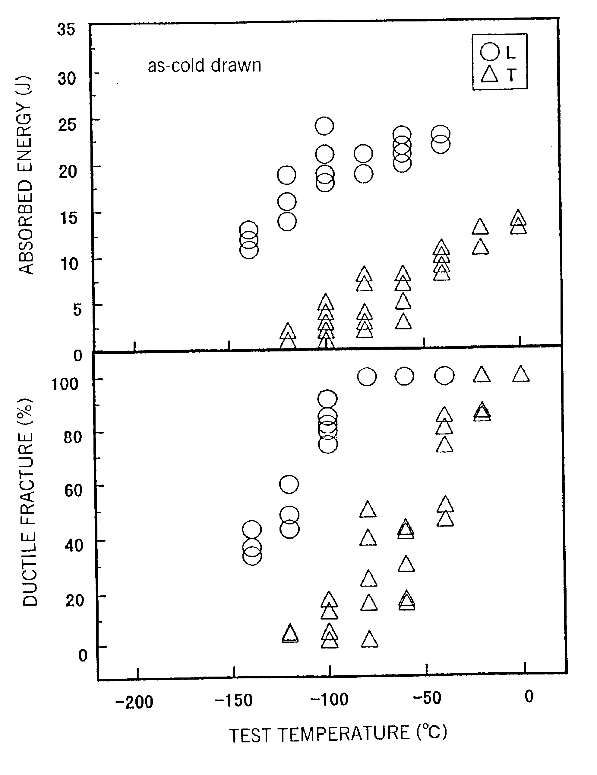
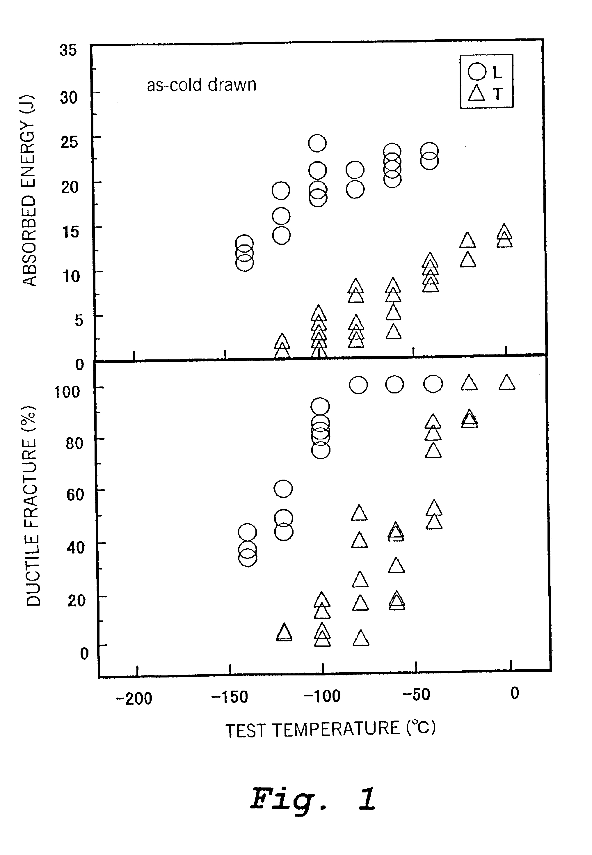
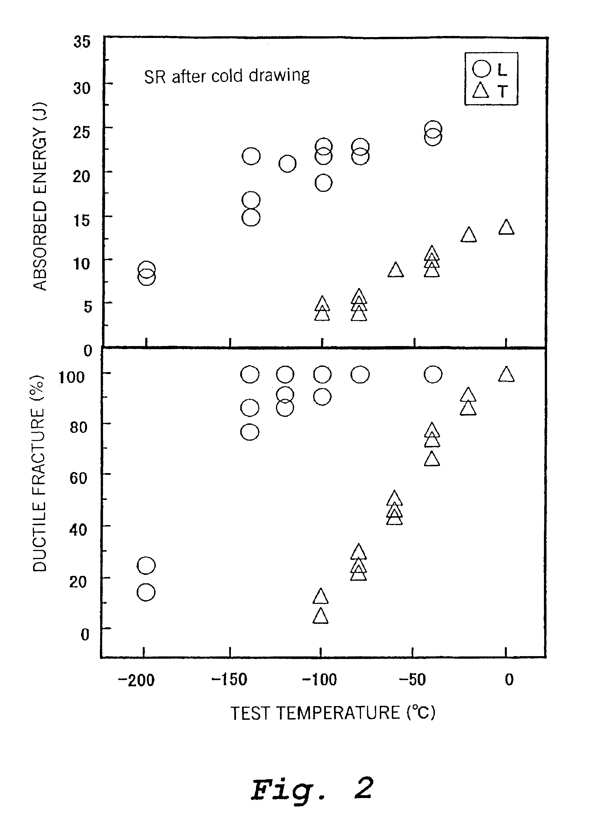
From a billet having the chemical composition shown in Table 2, a seamless steel pipe having an outer diameter of 70 mm and a wall thickness of 4.1 mm was produced by piercing and rolling using standard equipment of a Mannesmann piercer and a mandrel mill and it was then subjected to cold drawing in a conventional manner so as to have an outer diameter of 60.33 mm and a wall thickness of 3.35 mm.

TABLE 2Chemical Composition (mass %) Balance: Fe and impuritiesSteelCSiMnPSCrMoNiCuVa0.120.291.530.0080.0010.56————b0.110.311.320.0140.0010.610.320.270.21—c0.130.311.250.0170.0010.450.320.300.24—d0.120.301.350.017<0.0010.480.330.230.17—e0.100.281.290.015<0.0010.400.390.250.170.05f0.130.321.250.0140.0010.460.310.220.22—g0.100.311.320.0150.0010.420.38———h0.080.261.300.016<0.0010.470.360.280.22—i0.130.341.310.0150.0020.440.350.23——j0.130.781.320.0130.0010.470.32——0.03k0.090.821.280.0130.0010.440.320.230.22—l0.080.341.33*0.0350.0010.480.380.200.24—m0.090.301.300.014*0.0250.500.310...


PUM

PropertyMeasurementUnit
thicknessaaaaaaaaaa
outer diameteraaaaaaaaaa
tensile strengthaaaaaaaaaa

Abstract

In order to manufacture a steel pipe for an air bag which can cope with increase in the pressure of gas blown into an air bag and decreases in the wall thickness of an accumulator, a steel having a composition, mass %, of:C: 0.05-0.20%,Si: 0.1-1.0%,Mn: 0.20-2.0%,P: at most 0.025%,S: at most 0.010%,Cr: 0.05-1.0%,Al: at most 0.10%,if necessary at least one of Mo: at most 0.50%, Ni: at most 1.5%, Cu: at most 0.5%, V: at most 0.2%, Ti: at most 0.1%, Nb: at most 0.1%, and B: at most 0.005%, andalso if necessary, at least one of Ca: at most 0.01%, Mg: at most 0.01%, and REM (rare earth elements): at most 0.01%,and a remainder of Fe and impurities is used to produce a steel pipe, and the pipe is then subjected to cold working to predetermined dimensions, then to heating to a temperature of at least the Ac1 transformation temperature followed by quenching, and then to tempering at a temperature no higher than the Ac1 transformation temperature.

Description

TECHNICAL FIELDThis invention relates to a steel pipe for an air bag, a process for its manufacture, and an accumulator for an air bag. More particularly, it relates to a high strength steel pipe for an air bag in which the steel pipe has high dimensional accuracy and which is excellent with respect to workability and weldability and it has high strength and excellent resistance to bursting, a process for its manufacture, and an accumulator for an air bag.BACKGROUND ARTIn recent years, in the automotive industry, the introduction of apparatuses and systems aimed at the safety of automobiles has been actively promoted. Among these are air bag systems. These are systems which are mounted on an automobile and which, at the time of an automotive collision, expand an air bag with gas or the like between a steering wheel or an instrument panel or the like and a passenger before the passenger impacts therewith, and absorb the kinetic energy of the passenger with the object of reducing inju...

Claims


Application Information

Patent Timeline
Patent Type & Authority Patents(United States)
IPC IPC(8): C22C38/40C22C38/42C22C38/26C22C38/58C22C38/28C22C38/48C22C38/22C22C38/20C22C38/50C21D8/10B60R21/26C21D9/08C21D1/18B60R21/268
CPCC21D8/10C22C38/20C22C38/22C22C38/58C22C38/28C22C38/40C22C38/42C22C38/48C22C38/50C22C38/26B60R21/268C21D1/18C21D9/08
Inventor KONDO, KUNIOYAMAMOTO, MIYUKITAKANO, TAKASHIBEPPU, KENICHIHIRANO, SUSUMUHITOSHIO, KEISUKEKURATA, HIDETOSHI
Owner NIPPON STEEL CORP
Why Eureka
Try Eureka