Wastewater clarification methods and apparatus

a technology of wastewater and equipment, applied in the field of wastewater treatment, can solve the problems of biological solids not being recycled from the output stream of fixed-film digesters, sludge collection, and discharge of these materials into the environment with wastewater

Inactive Publication Date: 2005-04-12
BRENTWOOD INDS
View PDF4 Cites 10 Cited by
  • Summary
  • Abstract
  • Description
  • Claims
  • Application Information

AI Technical Summary

Benefits of technology

The invention relates to a wastewater clarifier comprising a vessel having an interior with a settling region above a biological solids collection region. The interior of the vessel has a mixing chamber in fluid communication with the settling region. The mixing chamber has a wastewater conduit for providing wastewater to the chamber and a recycle conduit for providing activated sludge from the biological solids collection region to the chamber. Wastewater and activated sludge provided to

Problems solved by technology

Discharge of these materials into the environment with the wastewater can have undesirable health and environmental consequences.
However, biological solids are not recycled from output streams of fixed-film-type digesters (e.g., trickling filters and submerged fixed-film biological treatment units), nor is sludge collected in a clarifier downstream from a fixed-film-type digester recycled into the biological reactor.
For instance, fixed-film biological reactors

Method used


Image

  • Wastewater clarification methods and apparatus
  • Wastewater clarification methods and apparatus
  • Wastewater clarification methods and apparatus

Examples


first embodiment

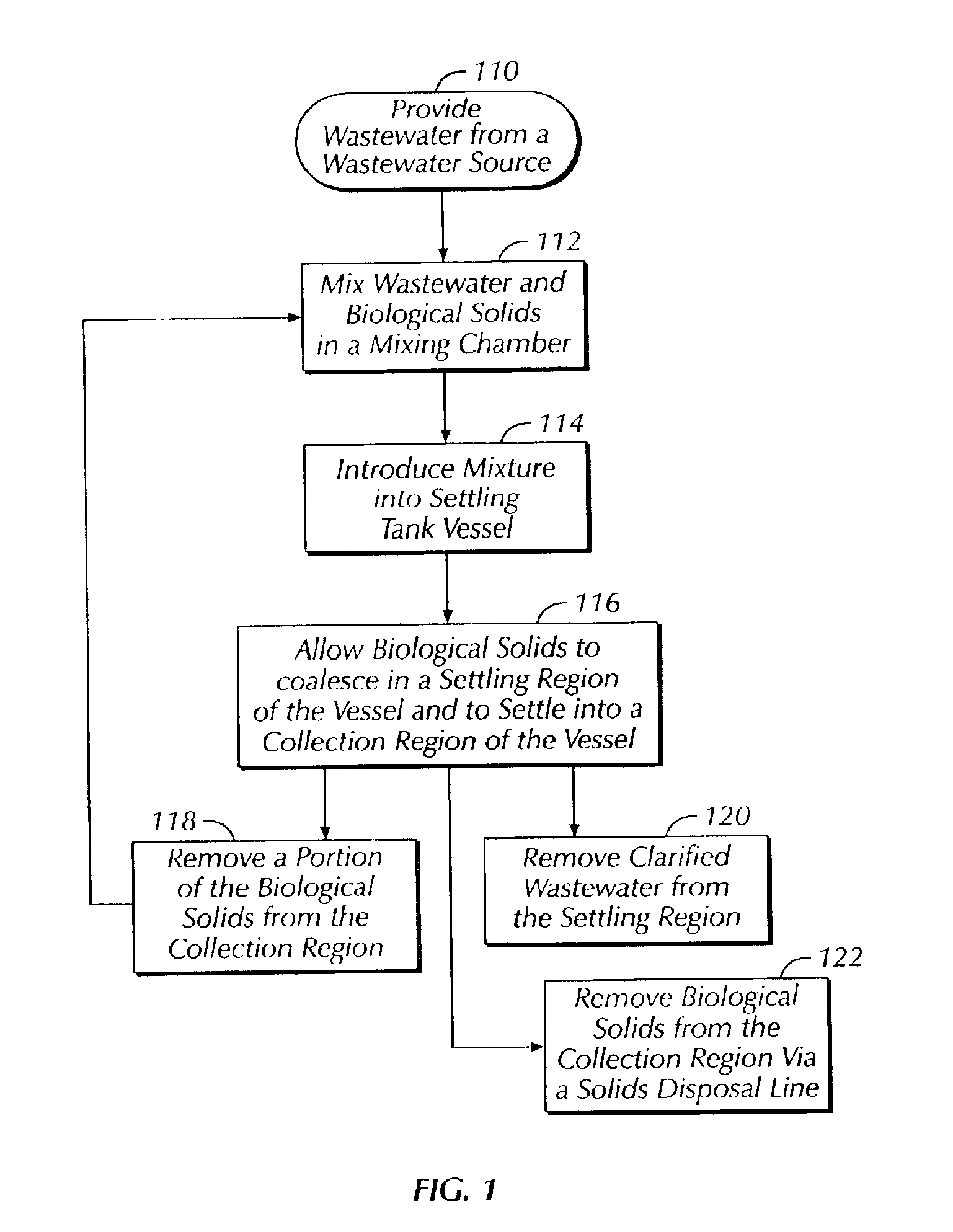
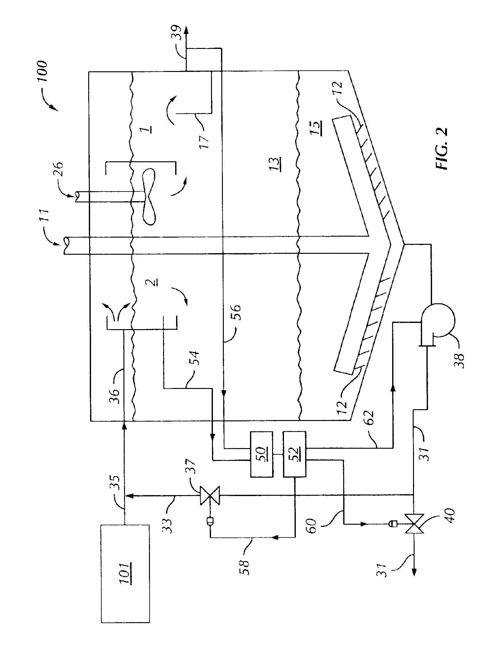
Improved wastewater clarifiers can be designed as described herein. Referring to FIG. 2, a wastewater clarifier 100 capable of being used in conjunction with the method of FIG. 1 is illustrated. The wastewater clarifier 100 comprises a vessel 1 and a mixing chamber 2. The mixing chamber 2 is in fluid communication with the vessel 1, and may be disposed within the vessel 1, maintained outside the vessel 1, or some combination of these two. The vessel 1 includes a settling region 13 and a biological solids collection region 15. A rotating rake assembly 11 extends into the collection region 15. Biological solids are removed from the vessel 1 by way of either or both of a solids disposal conduit 31 and a recycle conduit 33. Flow through the recycle conduit 33 is regulated in order to maintain an appropriate mixture with wastewater supplied from a wastewater source 101 by way of a wastewater conduit 35. Flow through the solids disposal conduit 31 is also regulated. Flow regulation in the...

second embodiment

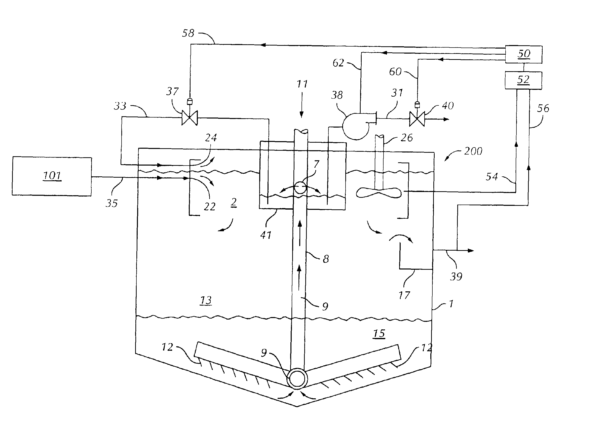
An alternative embodiment of the clarifier is shown in FIG. 3. In this second embodiment, a wastewater clarifier 200 has a sludge well 41 preferably disposed at least partially within the vessel 1, also preferably positioned concentrically within the vessel 1 and the mixing chamber 2. The rake 11 comprises a shaft 8 that comprises a hollow portion 9. A sludge well 41 sealingly surrounds a portion of the shaft 8 and extends above the liquid level in the vessel 1, thereby substantially isolating liquid in the sludge well 41 from liquid in other portions of the vessel 1. The hollow portion 9 of the rake shaft 8 has an orifice 7 in its wall within the sludge well 41, so that the interior of the sludge well 41 is in fluid communication with the interior of the hollow portion 9. The hollow portion 9 extends near the floor or bottom of the vessel 1 and facilitates liquid flow between the lower portion of the vessel 1 and the sludge well 41. A solids disposal conduit 31, shown having an in-...


PUM

PropertyMeasurementUnit
Weightaaaaaaaaaa
Weightaaaaaaaaaa
Massaaaaaaaaaa

Abstract

The invention relates to a liquid clarifier useful for removing solids suspended in a wastewater stream. Settled biological solids are taken from the clarifier and combined in a mixing chamber with a wastewater stream. The combined liquid is provided to a settling region of the clarifier, and suspended solids settle in a biological solids collection region, from which the solids are taken. Clarified liquid can be withdrawn or permitted to overflow from an outlet region in the settling region of the clarifier. The clarifier can enhance the degree of solids removal from wastewater streams having relatively low total suspended solids values, such as outlet streams from fixed film-type digesters. The clarifier is suitable for use in combination with other components of wastewater treatment systems, and can be included as a module in many kinds of wastewater treatment systems.

Description

BACKGROUND OF THE INVENTIONThe invention relates to treatment of wastewater from residential, business, industrial, or other sources.Wastewaters obtained from various sources can contain bulk solid materials (sticks, rags, sand, and other materials that can be screened or filtered therefrom), smaller suspended solid materials that cannot be easily removed by screening or filtration, degradable organic compounds (sometimes designated biological oxygen demand or “BOD”), pathogenic microorganisms (e.g., bacteria, viruses, spores, cysts, and protists), and undesirable nutrients (e.g., nitrogen- or phosphorous-containing compounds that can encourage nuisance growth of algae or weeds at the wastewater discharge site). Discharge of these materials into the environment with the wastewater can have undesirable health and environmental consequences. As a result, wastewater discharges are closely regulated by state and national governments.Many methods exist for removing undesirable components...

Claims


Application Information

Patent Timeline
IPC IPC(8): B01D21/02B01D21/04
CPCB01D21/04B01D21/245B01D21/2488B01D21/2483B01D21/32B01D21/34
Inventor MCDOWELL, CURTIS S.HANNUM, CHRISMAURER, ROBERT
Owner BRENTWOOD INDS
Why Eureka
Try Eureka