Method of fabricating sintered nuclear fuel compact

a nuclear fuel and compact technology, applied in the direction of manufacturing tools, nuclear elements, greenhouse gas reduction, etc., can solve the problem of too difficult control of yield and other problems

Inactive Publication Date: 2005-04-12
NUCLEAR FUEL INDS
View PDF6 Cites 6 Cited by
  • Summary
  • Abstract
  • Description
  • Claims
  • Application Information

AI Technical Summary

Benefits of technology

In this way, there is obtained a sintered nuclear fuel compact with a large grain diameter, whose average grain diame

Problems solved by technology

In order to render the grain diameter as large as the above, however, many parameters are thus necessitated to be adjusted and a strict temperature

Method used


Image

  • Method of fabricating sintered nuclear fuel compact
  • Method of fabricating sintered nuclear fuel compact
  • Method of fabricating sintered nuclear fuel compact

Examples


example 1

Uranium dioxide starting material powder, 70% by weight, and 30% by weight of triuranium octaoxide roasted at 400° C. were mixed together, and the resulting mixture was compacted and subjected to sintering treatment in a batch type furnace in an oxidizing atmosphere of N2 / O2 gas for 4 hours and subsequently to reduction treatment by heating in a reducing atmosphere of H2 gas for 2 hours. A sintered compact of uranium dioxide series nuclear fuel was thus fabricated.

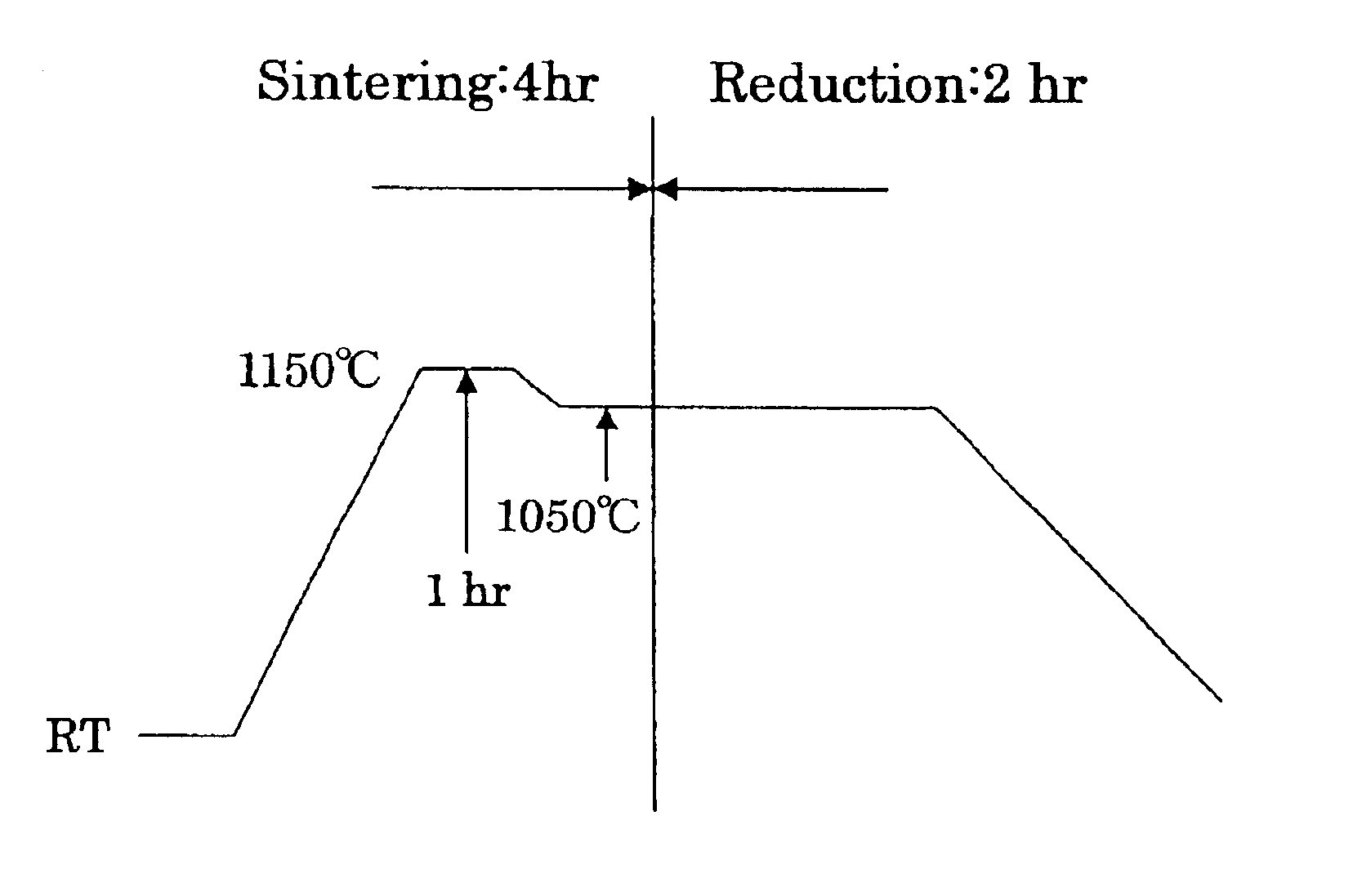
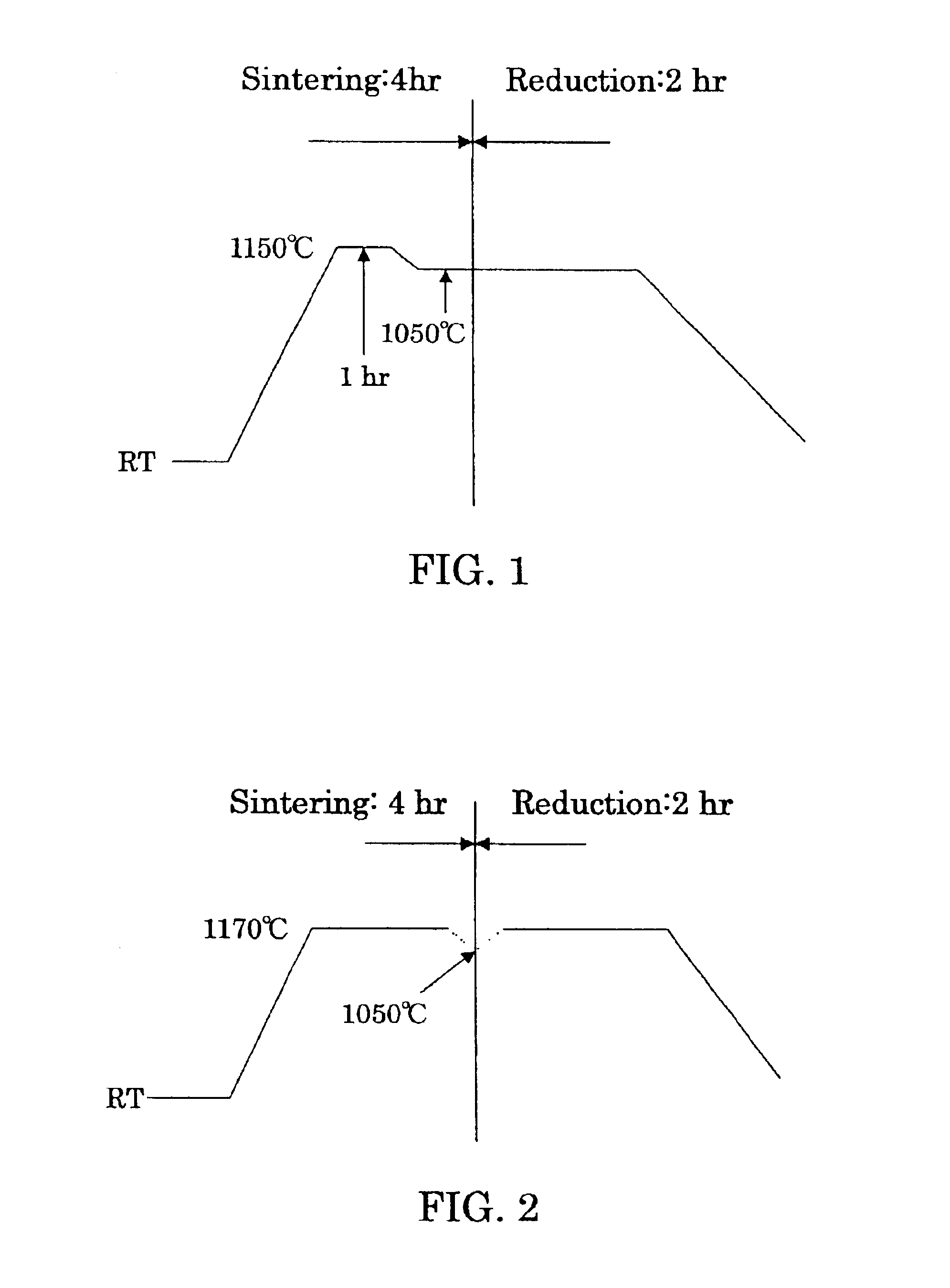
At that time, as shown in FIG. 1, during the oxidizing sintering stage, the temperature was raised to 1150° C., maintained at 1150° C. for 1 hour, and then depressed to 1050° C., at which temperature the sintering stage entered into the reduction stage. In this example, one time of temperature rise and one time of temperature drop were thus performed at the beginning of and in the course of the sintering, respectively. The sintered compact thus obtained was, as shown in FIG. 5, of much larger grain diameter pellets (ca. 80...

example 2

A sintered nuclear fuel product was likewise prepared as in Example 1 above except that during the sintering treatment in the oxidizing atmosphere, the temperature was raised to 1170° C. and, at the end of the oxidizing sintering, was depressed from 1170° C. to 1050° C., as shown in FIG. 2, followed by shifting to the reduction process. In this case, one time of temperature rise and one time of temperature drop are undergone at the beginning of and at the end of the sintering in the oxidizing atmosphere. The sintered compact thus obtained had an intended large grain diameter (ca. 60 μm), as is apparent from FIG. 6.

example 3

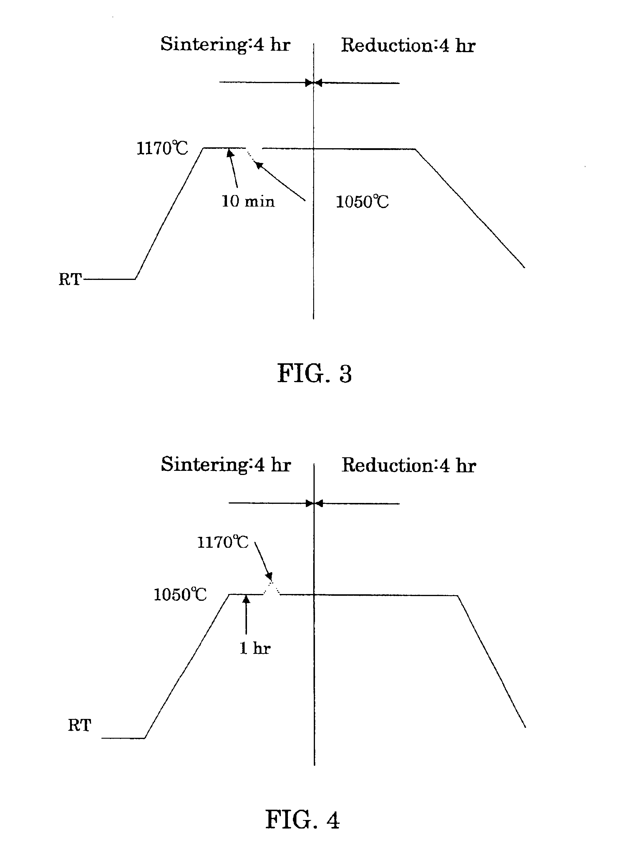
A sintered nuclear fuel compact was likewise prepared as in Example 1, except that during the sintering treatment in the oxidizing atmosphere, as shown in FIG. 3, the temperature was raised to 1170° C. and maintained at 1170° C. for 10 minutes, and thereafter, the temperature was once depressed to 1050° C. and again reverted to 1170° C.; and the reduction treatment was performed for 4 hours instead of 2 hours. Here, three times, in total, of temperature changes including one time of temperature rise at the beginning of the treatment, one time of temperature fall in the midst of the treatment and one time of temperature rise at the end were thus undergone. The sintered compact obtained in this way had a large grain diameter (ca. 50 μm) as shown in FIG. 7.


PUM

PropertyMeasurementUnit
Temperatureaaaaaaaaaa

Abstract

To furnish stably a sintered nuclear fuel compact of uranium dioxide with a large grain diameter, a fabrication method therefor requires sintering a starting material at two stages in an oxidizing atmosphere and in a reducing atmosphere at relatively low temperatures. The starting material is either a powder mixture of uranium dioxide fresh material powder and triuranium octaoxide in a weight ratio of 75/25 ˜ 55/45 or pulverulent mixed uranium oxides yielding a final O/U ratio equal to that of the powder mixture. The sintering process in the oxidizing atmosphere involves at least one time period of a temperature rise to a higher temperature of 1200 to 1100° C. and at least one time period of a temperature drop to a lower temperature of up to 1080° C. A temperature difference between the higher and lower temperatures is preferred to be 50° C. or more.

Description

BACKGROUND OF THE INVENTION1. Field of the InventionThis invention relates to a low-temperature method of fabricating a sintered nuclear fuel compact of uranium dioxide with a large grain diameter and more particularly, to an improved method of fabricating a sintered nuclear fuel compact which comprises preparing large grain size pellets stably by two-stage sintering in an oxidizing atmosphere at relatively different low temperatures and in a reducing atmosphere.2. Description of the Related ArtA low-temperature sintering method for such nuclear fuel pellets is known, which can be carried out at a relatively low temperature on the order of 1100 to 1300° C., in contrast to a conventional sintering method of a nuclear fuel material which was conducted at around 1700° C. In general, low-temperature methods having recourse to a two-stage sintering, which includes sintering in an oxidizing atmosphere and subsequent reduction heating, have been widely known.For example, JP Patent Publicat...

Claims


Application Information

Patent Timeline
IPC IPC(8): G21C21/00G21C3/62G21C3/42G06F9/44
CPCG21C3/623G21C21/00Y02E30/38Y02E30/30
Inventor KOBAYASHI, SHIN-ICHIFUKUMOTO, KATSUO
Owner NUCLEAR FUEL INDS
Why Eureka
Try Eureka